Recent dissonnace about LCA radome shows need to unnderstand this crucial technology.
What is a radome?
Why do planes needed it?
How are they made?
What is the level of expertise in India?
What has already been made in India?
Why was Cobham chosen for LCA, MMR radar?
What raw materials are used in radome and availability in India?
thanks, ramana
Project BRF: Radome technology in India
Re: Project BRF: Radome technology in India
What is radome?
We confine ourselves for aircraft forward nose cone radomes.
https://en.wikipedia.org/wiki/RadomeA radome (which is a portmanteau of radar and dome) is a structural, weatherproof enclosure that protects a microwave (e.g. radar) antenna. The radome is constructed of material that minimally attenuates the electromagnetic signal transmitted or received by the antenna. In other words, the radome is transparent to radar or radio waves. Radomes protect the antenna surfaces from weather and conceal antenna electronic equipment from public view....
Radomes can be constructed in several shapes (spherical, geodesic, planar, etc.) depending upon the particular application using various construction materials (fibreglass, PTFE-coated fabric, etc.).
When found on fixed-wing aircraft with forward-looking radar (as are commonly used for object or weather detection),[1] the nose cones often additionally serve as radomes.
We confine ourselves for aircraft forward nose cone radomes.
-
member_20292
- BRF Oldie
- Posts: 2059
- Joined: 11 Aug 2016 06:14
Re: Project BRF: Radome technology in India
Awesome thread.
And if we can crowd source research proposals and technical development to make better radomes for the LCA , then this thread will be doubly awesome.
And if we can crowd source research proposals and technical development to make better radomes for the LCA , then this thread will be doubly awesome.
Re: Project BRF: Radome technology in India
MB As you are materials guru from most awesome gurukul in that are can you dig up RF transparency properties for typical materials used for radomes. Also structural properties like Young's modulus and ultimate strength.
Re: Project BRF: Radome technology in India
Circa 2010 on Jaguar Radome:
http://forums.bharat-rakshak.com/viewto ... 88#p865588
http://forums.bharat-rakshak.com/viewto ... 88#p865588
TOT(Transfer of Technology) Document on Jaguar Nose Radome Fabrication handed over to HAL
NAL indigenously designed, developed and fabricated a composite nose radome for the Fire Control Radar of Jaguar Maritime Aircraft for HAL, Bangalore, end user being IAF. In continuation to the development of 11 no. nose radomes, a request was made by HAL – Overhaul Division for transfer of technology of the Jaguar Nose Radome fabrication.
The TOT document was officially handed over to HAL by Director, NAL on 16th April 2010 at a small function held at Director’s Conference Hall. NAL had undertaken this project with FRP Division as a nodal point and coordinating the overall activities with interdivisional participation by CEM Lab., ALD, Structural Technologies Division, CTFD and Engineering Services Division. HAL supported the fabrication and supply of all metallic parts, inserts and structural static tests. CABS supported in lightning protection tests. LRDE, CATF-ISRO and IAI – Elta, Isreal for EM tests. The vibration test was carried out at STTD, NAL. The radome had gone through a systematic development right from structural design, fabrication, full qualification tests, including flight tests and ATP tests on all production radomes.
It is a variable thickness, nose thick and base thin design radome. An inhouse developed closed mould resin injection technology has been used in fabrication of the radome. The composite radome is protected with anti-static / anti rain erosion paint subjected to qualification tests, viz., EM, lightning protection, static loading, vibration and rain erosion tests in presence of CRI.
From the HAL side, Wg. Cdr. MP Benjamin , DGM, Overhaul Division received the TOT documents and mentioned that it was an auspicious day for both HAL and NAL. He stated that HAL is accepting technology transfer for the first time and expressed it as a honour to take the TOT document to HAL on behalf of their GM Mr. KG Subramony.
In the light of IAF planning to deploy around 50 Jaguar aircrafts to its fleet with fire control radars, it is apt that this technology transfer of indigenously developed nose radome from NAL to HAL is befitting. Wg. Cdr. Benjamin stated that tentatively the first radome of the 50 nos. should be ready by June 2011. He also assured that once the Mirage aircrafts get inducted and serve the IAF, HAL may come back to NAL for indigenising its radome.
[Did Mirage request happen? ramana}
Director, NAL congratulated the team for the successful execution of a national project leading to a technology transfer by CSIR-NAL to a Public Sector and in turn to the nations defence sector – the IAF.
Shri DV Venkatasubramanyam, Head, FRPD also spelt a word of appreciation to all those involved in this project and some of them who had superannuated to name a few Shri SK Veluswamy, Shri Ranganath Rao, Shri Sathyanarayan of HAL, Dr. S Christopher of LRDE, Dr. RMVGK Rao, Dr. S Viswanath, Shri C Chandrashekar and Shri Dwarakanath of NAL, Shri Majeed and Shri VL Raja of CRI-CEMILAC whose contributions need to be mentioned on this occasion.
The event was graced by Dr. Ranjan Moothithaya, Head, KTMD and team, Head, CTFD & team, Head, CEM Lab., ALD, Head, Engineering Services Division and the FRP team.
It was a moment of pride to NAL as it also marked yet another milestone on the map of CSIR-NAL’s achievements. The Jaguar Nose Radome Project team thanked the Director, NAL, on this occasion.
Re: Project BRF: Radome technology in India
Look @ Cobham formerly known as Fligh Refuelling Inc>
Link Radome and composies
Not much really. I am looking for power and Band.
https://en.wikipedia.org/wiki/EL/M-2052
and
http://www.iai.co.il/2013/34481-34455-en/IAI.aspx
Looks like variable power based on antenna! 3-10 kVA
So LCA application assume ~5 kVA
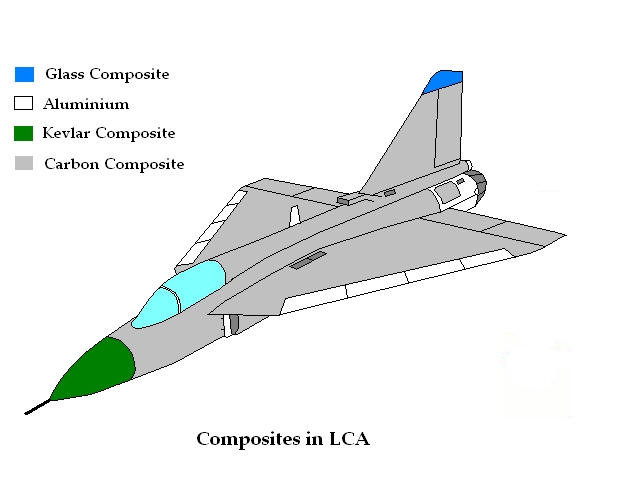
Also LCa always planned for a kevlar radome as shown here
Link Radome and composies
EL/M 2052 Radar specs:Radomes and Composites
Cobham radomes can be found on virtually all airborne military platforms flying today. In addition to military aircraft, Cobham radomes can be found on shipboard, ground based, unmanned systems, submarine, and munitions applications.
Cobham radomes are made from composite materials in our state-of-the-art composite facility. In this facility, we have an environmentally controlled lay-up room, paint booths, autoclaves, ovens, tooling department and a 5-axis CNC machining center. Our radomes use the most optimal materials for the given applications. Our radome designs include solid wall, A-sandwich and multi-layer construction and can be tailored to virtually all typical frequencies. The materials and construction are chosen to minimize loss at the specific frequency while optimizing strength and cost.
Typical Cobham radomes use fibers of E-glass, S-glass or Quartz and resins of BMI, cyanate ester, polyester, and epoxy. Finally, Defence Electronics has expertise in all types of radome coatings, including epoxies, polyurethanes, fluoroelastomers, and anti-static topcoats.
The following table provides a partial list of models, frequency ranges and general specifications. To review detailed specification sheets in PDF format, click on the composite model desired.
Please fill out and submit our Basic Radome Parameters (pdf - 540KB) for all your custom design needs.
Not much really. I am looking for power and Band.
https://en.wikipedia.org/wiki/EL/M-2052
and
http://www.iai.co.il/2013/34481-34455-en/IAI.aspx
Looks like variable power based on antenna! 3-10 kVA
So LCA application assume ~5 kVA
Also LCa always planned for a kevlar radome as shown here
Re: Project BRF: Radome technology in India
LCA MMR from a blog:
http://lca-tejas.blogspot.com/2006/02/mmr-radar.html
- Kevlar Radome did not perform leading decision on quartz version by Cobham.
Same time EL/M 2052 is being used.
Next will look at who else designs and makes radomes inn India.
http://lca-tejas.blogspot.com/2006/02/mmr-radar.html
- MMR did was unsuccessful leading EL/M2032 being incorporated.Monday, February 13, 2006
The MMR Radar
The Multi Mode Radar or MMR is the primary sensor of the Tejas and will take care of take care of detection, tracking, terrain mapping and delivery of guided weapons.
The MMR is the result of a joint developmental effort of HAL, Hyderabad and LRDE, Bangalore. Drawing upon over 15 years of research, the MMR is India’s first airborne monopulse doppler multimode radar.
The MMR is a mechanically scanned radar with a planar antenna and operates in the X band. The radar is very light in weight and has four major subsystems : the antenna and associated stabilisation system with drive assembly, power amplifier, exciter-receiver, signal/data processing unit.
The antenna is a light weight (less than 5kg), low profile slotted waveguide array and has a diameter of 650mm. It has upto 4 stacks of compact state of the art slotted wave guides which have been designed using CAD software packages and manufactured using computer numerically controlled slot machining and fabrication, dip and vacuum braising. This ensures that the main beam produced is of very high gain and the side lobes are of very low levels. The MMR antenna also features a multi-layered feed network for broad band operation.
Employing a high power output and low/medium/high repetition frequencies, the air to air mode includes – Multi target velocity search, track while scan(TWS), priority tracking and single target track(STT). The MMR achieves a detection range of 100km for typical airborne fighter sized targets (~5 sq.m RCS) .
The track-while-scan feature keeps track of multiple targets (maximum of 10 targets) and also engagement of multiple targets simentaneously . 2 targets can be tracked in the priority track mode and a continuous high quality track of a single target is possible in the STT mode.
The air to ground mode includes – terrain following, terrain/obstacle avoidance, real ground mapping with Doppler beam sharpening. The terrain following and obstacle avoidance modes allow flight down to 100km, facilitating potential flight with cover from enemy ground radar.
The air to sea mode includes sea surface target search and track.
The antenna scan limits are restricted to plus/minus 70 degrees in azimuth and to plus/minus 60 degrees elevation.
Other features of the MMR include integrated Identification of Friend or Foe (IFF) system, and GUARD and BITE channels. Pulse-Doppler gives the MMR look-down shoot-down capability. Ground mapping feature, frequency agility and other ECCM techniques make the radar truly state-of-the-art.
MMR Signal Processor
The heart of MMR is the signal processor, which is built around VLSI-ASICs and i960 processors to meet the functional needs of MMR in different modes of its operation. Its role is to process the radar receiver output, detect and locate targets, create ground maps, and provide contour maps to the pilot when the feature selected.
The post-detection processor resolves range and Doppler ambiguities and forms plots for the subsequent data processor. The special feature of the signal processor is its real-time configurability to adapt to requirements depending on selected mode of operation. Advanced signal processing algorithms and tracking filters ensure good performance against high speed and extensively maneuvering targets.
Other generic functions of the signal processor include: Detection of airborne and surface targets by employing LPRF/MPRF/HPRF waveforms depending on the selected mode, Platform motion compensation, MTI and Doppler filtering, CFAR detection, Range-Doppler ambiguity selection, Scan conversion, Display of target and ground maps on the Multi Function Displays (MFD’s), real-time configurability and Online diagnostics to identify faulty processor modes.
MMR Pulse Coupled Cavity TWT – MPC 4068
The MPC 4068 is an inverted slot mode coupled cavity (inter digital) TWT with a non-intercepting griddled gun, PPM focussing, single stage depressed collector and liquid cooling that has been developed by the Microwave Tube Research and Development Centre (MTRDC). It has a high gain of 38dB, high efficiency, and a high spectral purity even when under heavy vibration. It is of small size with dimensions of 370x160x120mm and weighs 6.5kg. Electrical connections are made through flying leads and cooling is done with liquid Coolanol flowing at 15 lpm. The peak output of the TWT is 6.5kW and has a duty cycle of 10%.
posted by Samartha at 2:12 AM
- Kevlar Radome did not perform leading decision on quartz version by Cobham.
Same time EL/M 2052 is being used.
Next will look at who else designs and makes radomes inn India.
Re: Project BRF: Radome technology in India
From CAG repor on LCA
Page 31:
MMR delays
Page 31:
Page 32:i. Development of Radome
The Radome is a primary structure on an aircraft, which houses the antenna. It
Radome developed needed to possess electro-magnetic
by ASL and manufactured by (EM) transparency to get the best
HAL was not found performance of the Antenna as well as
suitable for LCA and imported Radome is structural integrity.
The Radome yet to be tested along with MMR for assessing its performance.
Radome designed and developed by the Advance
Systems Laboratory (ASL), Hyderabad
was selected (December 1989) for the
LCA prototypes.
Page 33:Manufacturing of Radomes was started (June 2008) in HAL and the Regional
Centre for Military Airworthiness (Aircraft), Bangalore accorded structural
clearance (October 2009) to Radome manufactured by HAL. The first
Electromagnetic test result of production Radome, supplied (December 2011)
by HAL showed (June 2012) high loss of signal power resulting in significant
reduction in radar range thereby affecting its performance. The Empowered
Committee (June 2013) noticed that the losses of signal power were due to
design deficiency and choice of Kevlar3 material. Subsequently, due to this
deficiency, ADA had to conclude (September 2013) a contract with M/s
Cobham, England for development and supply of six Radomes4 with quartz
material at a cost of GBP 2.5 million (`22.75 crore) by January 2015 for
testing on LCA.
Thus, ADA has to depend on imported source for meeting the requirement of
Radome as the one developed indigenously by ASL, Hyderabad and
manufactured by HAL was not found suitable for LCA. This had impacted
testing of MMR with cascading effect on accomplishment of FOC.
MMR delays
he joint indigenous development of MMR for LCA was
entrusted (June 1991) to M/s HAL,6 Hyderabad Division
and LRDE7, Bangalore at a cost of `62.27 crore
(FE `35.374 crore), to be completed by December 1997.
The delay in development of MMR despite consultancy
from Ericsson and consequent import of three antenna
MMR Test Rig
were commented in Paragraph No 28 of Report of C&AG
of India for the year ended March 1998 (No 8 of 1999).
However, Ministry’s reply was silent on this aspect while furnishing (July
2004) the ATN.
The MMR developed by HAL/LRDE was found (2006) short of expectations.
Subsequently ADA concluded (October 2006) a contract with M/s Elta Israel
for co- development/ consultancy, supply & integration of MMR on LCA at a
cost of 26.5 Million USD (`119.25 crore) by June 2009. Though the MMR
was ready by 2009 for integration on LCA, the LCA (LSP3) required
structural changes in front fuselage for installation of MMR LRUs. After the
LSP3 was ready in 2010, the MMR was put to functionality and performance
testing. While the functionality testing of MMR was completed in December
2013, it could not be cleared in performance testing.
To an audit observation (October 2014) seeking reasons for delay in testing of
MMR and resultant impact on IOC/FOC schedule of LCA, ADA stated
(October 2014) that the MMR required several software updates during its
development, which contributed to delay apart from non-availability of aircraft
for testing. As regards availability of MMR for IOC achieved in December
2013, ADA stated (October 2014) that though MMR was integrated on LCA
at the time of IOC, certain performance requirements such as range
performance was falling short due to Radio Frequency (RF) losses of Radome
and these limitations were recorded as part of Release to Service Document
(RSD) of IOC of LCA. This had resulted in ADA concluding a fresh contract
with M/s Cobham for an improved Radome with quartz material as has been
discussed in sub-para 3.1 (ii).
As MMR performance could not be proven due to change in Radome, ADA
had to obtain (December 2013) concession from Air HQ while obtaining IOC
for LCA. As discussed in Para 2.3, Air HQ while commenting (December
2014) on impact of concessions on the combat potential of LCA, had stated
with regard to non-evaluation of MMR that ‘Delay in addressing the issue
would have an adverse impact on combat employability of LCA’.
Thus, indigenous development of MMR for LCA could not be accomplished
even after 22 years. Further, pending testing of MMR with the newly
developed Radome, the performance testing and integration of MMR would
remain incomplete, which would impact the combat employability of LCA.
Re: Project BRF: Radome technology in India
Key electrical properties for radome laminate are Dielectric Constant and Loss Tangent or Coefficient
You also want low specific gravity so whole thing weighs less and low moisture absorption to prevent loss in transmission.
Above two are important for LCA in tropical India!!!
Here is a website of a US company that makes such materials:
http://www.azom.com/article.aspx?ArticleID=7984
Kevlar isn't bad but for its moisture absorption.
And weighs less too.
Re: Project BRF: Radome technology in India
Microwave Journal
Efficient design and analysis of airborne radomes
Gives good background for our use.
http://www.microwavejournal.com/article ... ne-radomes
Clean link sans ads! Use above.
Efficient design and analysis of airborne radomes
Gives good background for our use.
http://www.microwavejournal.com/article ... ne-radomes
Clean link sans ads! Use above.
Re: Project BRF: Radome technology in India
Above paper employs FEKO from Altair. Here is a link to metamaterials (which are usually nade of carbon composite layers and are characterized by anisotropic properties) simulation capabilities of FEKO.
FEKO for special materials
FEKO for special materials
Re: Project BRF: Radome technology in India
This is a structures-EM-Thermal coupled problem with material and EM properties being anisotropic due to the radome being made of carbon composite material. Here is a link to different methods and further links to packages - both open source and commercial - to solve EM problems.
FMM is was invented by Greengard and (his adviser) Rokhlin of Yale University in the early 1990s. His thesis has been published IIRC as a book by MIT Press. Several implementations are around. Greengard is a professor at NYU.
(Added Thermal. Don't know whether the energy of radiation involved is high enough that thermal stresses need to be considered as well)
Re: Project BRF: Radome technology in India
VT Tejas radome is quartz fiber with cynate ester or BMI resin. Cobham has expefince in this per their own website.
NAL has the EM solvers. And hass built quartz fiber radomes with polyester resin which is lower temp capability.
I think problem is EL/M 2032 being operated with less number of TRTs.
Problem goes away in Uttam version.
NAL has the EM solvers. And hass built quartz fiber radomes with polyester resin which is lower temp capability.
I think problem is EL/M 2032 being operated with less number of TRTs.
Problem goes away in Uttam version.
Re: Project BRF: Radome technology in India
ramana garu: Thanks for the pointer. I will have to do a little bit more reading to understand "quartz fiber with cynate ester or BMI resin" as you put it.
Are the properties - thermal, mechanical, and EM - are homogeneous?
Are the properties - thermal, mechanical, and EM - are homogeneous?
Re: Project BRF: Radome technology in India
Mechanical with temperature. BMI has high temperature strength. Quartz fiber has very good transmissibility and loss tangent with zero moisture absorption.
But costs more.
http://www.netcomposites.com/guide/other-resins/19
But costs more.
http://www.netcomposites.com/guide/other-resins/19
Besides polyesters, vinylesters and epoxies there are a number of other thermosetting resin systems that are used where their unique properties are required:
Phenolics
Primarily used where high fire-resistance is required, phenolics also retain their properties well at elevated temperatures. For room-temperature curing materials, corrosive acids are used which leads to unpleasant handling. The condensation nature of their curing process tends to lead to the inclusion of many voids and surface defects, and the resins tend to be brittle and do not have high mechanical properties. Typical costs: £2-4/kg.
Cyanate Esters
Primarily used in the aerospace industry. The material's excellent dielectric properties make it very suitable for use with low dielectric fibres such as quartz for the manufacture of radomes. The material also has temperature stability up to around 200°C wet. Typical costs: £40/kg.
Polyurethanes
High toughness materials, sometimes hybridised with other resins, due to relatively low laminate mechanical properties in compression. Uses harmful isocyanates as curing agent. Typical costs: £2-8/kg
Bismaleimides (BMI)
Primarily used in aircraft composites where operation at higher temperatures (230°C wet/250°C dry) is required. e.g. engine inlets, high-speed aircraft flight surfaces. Typical costs: >£50/kg.
Polyimides
Used where operation at higher temperatures than bismaleimides can stand is required (use up to 250°C wet/300°C dry). Typical applications include missile and aero-engine components. Extremely expensive resin (>£80/kg), which uses toxic raw materials in its manufacture. Polyimides also tend to be hard to process due to their condensation reaction emitting water during cure, and are relatively brittle when cured. PMR15 and LaRC160 are two of the most commonly used polyimides for composites.
Re: Project BRF: Radome technology in India
before we analyze radome, some good refs for people like me:
https://en.wikipedia.org/wiki/Attenuation
which I suspect the main issue with our radome
I think we should also consider "Attenuation" here.radar fundas: http://faculty.nps.edu/jenn/Seminars/Ra ... entals.pdf
https://books.google.com/books?id=0itzo5h8O68C&lpg
considering anaprop (analogous propagation) is needed because a raptor or J31 or even a rafale/ef2k in the near space can be detected from their deflected signals.
signal processing algos needs to be advanced if we are handling side lobes, besides the point.
https://en.wikipedia.org/wiki/Attenuation
which I suspect the main issue with our radome
Re: Project BRF: Radome technology in India
Attenuation is the show stopper in LCA is what I heard. Either Quartz fiber bi is the culprit or the radar array design. Those are the only possibilities.
Re: Project BRF: Radome technology in India
Radar array design for ELTA/M -2032 works in other areas.
The number of emitters is the issue. Not enough power to transmit.
Quartz fiber chosen for better loss coefficient.
Also note LCA Mk1.5 will have Uttam which is ELTA/M 2052.
Makes sense.
However am flummoxed by Cobham being unable to deliver quality product.
The number of emitters is the issue. Not enough power to transmit.
Quartz fiber chosen for better loss coefficient.
Also note LCA Mk1.5 will have Uttam which is ELTA/M 2052.
Makes sense.
However am flummoxed by Cobham being unable to deliver quality product.
Re: Project BRF: Radome technology in India
To corroborate above conclusion here is link posted by tsarkar:
The design deficiency is current radar with Kevlar radome. Does not have enough signal power due to attenuation.http://www.saiindia.gov.in/english/home ... of2015.pdf
RWR fitted on LCA Mk-I is having issues such as degradation of direction finding accuracy, reset in air, etc and DARE is in the process of resolving these issues.CMDS fitted on LCA Mk-I exhibited deficiency in misguiding enemy missiles and ADA/BDL are in the process of modifying the design to overcome the flaw.The first Electromagnetic test result of production Radome, supplied (December 2011) by HAL showed (June 2012) high loss of signal power resulting in significant reduction in radar range thereby affecting its performance. The Empowered Committee (June 2013) noticed that the losses of signal power were due to design deficiency and choice of Kevlar3 material. Subsequently, due to this deficiency, ADA had to conclude (September 2013) a contract with M/s Cobham, England for development and supply of six Radomes with quartz4 material at a cost of GBP 2.5 million (`22.75 crore) by January 2015 for testing on LCA.
Re: Project BRF: Radome technology in India
kevlar is lighter isn't it? I will have to check the materials data base you linked above. So the ideal solution would be to be able to correct the design for kevlar radome.
Re: Project BRF: Radome technology in India
VT per the report from @SJha, Dr. Tamilmani said even quartz radome from Cobham did not offer relief.
Its linked in the LCA thread.....
Its linked in the LCA thread.....
Re: Project BRF: Radome technology in India
I scanned that part in LCA thread. Looks like the output power (by extension the input power) was not enough. One way is to experiment (in simulation only) with different array configurations and different kevlar layering.
Re: Project BRF: Radome technology in India
well, re: power, they must hook|crook must supply.. have a new mini turbine for it if need be., perhaps doing a dual purpose of TVC and radar ops like in the JSF (vtol+radar) designs.. this could be like wing mounted tvc/just saying/assumptions.
the point being, they should focus on higher powered AlGaN or GaN t/rs, and also increase the number of them. LRDE is already on this.. and should be the first option for LCA Mk2.
http://www.researchgate.net/publication ... evolutions

the point being, they should focus on higher powered AlGaN or GaN t/rs, and also increase the number of them. LRDE is already on this.. and should be the first option for LCA Mk2.
http://www.researchgate.net/publication ... evolutions
Re: Project BRF: Radome technology in India
SaiK: Conformal is on the side of a missile. The array for LCA is inside the radome.
Re: Project BRF: Radome technology in India
http://forums.bharat-rakshak.com/viewto ... 8#p1852928
relevant quote on radome here
relevant quote on radome here
However FOC for the Tejas Mk-I is now expected to be achieved only by late 2015. This, according to Dr K. Tamilmani, Director General (Aero),DRDO, is chiefly on account of delays in receiving two significant parts from an overseas vendor that will need to be certified for FOC acceptance. These are of course a bolt on inflight refuelling (IFR) probe and a new quartz nose cone radome, both of which are being procured from different divisions of UK's Cobham. While the Tejas program was earlier expecting to receive the IFR probe by September 2014 and the quartz nose cone by November 2014, it seems that the probe will only reach Indian shores by the end of January 2015 and the first of a total three units of the new nose cone will arrive a month or so later. It is understood that IAF teams have been making visits to Cobham to lean on them to deliver these items faster.
'If Cobham had kept its delivery timelines, the idea was to wrap up ground check outs for the IFR probe in October-November and then commence flight trials says. Some 20-25 day/night flights at different altitudes and speeds would be needed to clear the IFR system and had the probe been delivered in September, it would have easily been cleared before mid-2015', says Dr Tamilmani . He also says that adding the probe itself and flying it is not an issue since it has already been integrated on the hi-fidelity Tejas simulator developed by DRDO's Aeronautical Development Establishment (ADE) and has even been flown by test-pilots on it.
Now the new quartz nose cone supplied by Cobham replaces an indigenous one and is expected to help the Mk-I's multi-mode radar (MMR) (which has an indigenous antenna and scanner but an Elta EL/M-2032 processing back end) achieve 60 per cent more range than with the latter.The indigenous nose cone has of course already been fully qualified for all modes of the MMR but the current loss through this composite part limits the MMR's detection range to around 50 kms for a fighter sized target and this is expected to increase to more than 80 kms with the new quartz nose cone.
80/50 = 1.6 i.e 60 % more range and not 15% as Tarmak Chat with former ADA director suggested.
According to Dr Tamilmani, the first nose cone that Cobham made 'had problems' with appreciable losses which led them to making a second cone that is still undergoing structural load tests in the UK. This second nose cone will be supplied to India only in February 2015 and besides spot checks some 50 sorties will have to be flown to qualify this new nose cone. Though three Tejas flight vehicles outfitted with the MMR are ready to receive the new quartz nose cones, the delivery schedule is staggered with the remaining two being delivered at an interval of a month each after the first one. So as per Dr Tamilmani, there are no technological issues deferring FOC but merely process related ones subject to the vagaries of the foreign supplier for the two aforesaid parts.
Re: Project BRF: Radome technology in India
eklavya wrote:Derby range is also 50 km:srai wrote:Forget about MiG-21/27s. Even Mirage-2000s with its Super-530D and its MICA can't engage targets beyond that 60km mark.
https://en.m.wikipedia.org/wiki/Python_(missile)
EL/M-2032 range is apparently 150 km:
https://en.m.wikipedia.org/wiki/EL/M-2032
RDY range is apparently 140 km, RDY-2 potentially higher:
http://www.mirage-jet.com/Variants/DASH5/RDY/rdy.htm
Exploiting the full potential of the EL/M-2032 is obviously important to maximise situational awareness and to give the pilot the best opportunity to win any engagement.
Re: Project BRF: Radome technology in India
I think we have some numbers to analyze. With due assumptions.
#1 Range is representative of power transmitted.
1) EL/M 2032 has arrange of 150km. Most likely without any radome.
2) Stated range with Kevlar Radome is 50km.
3) Desired range with Quartz radome is 80 km.
Assessment:
Power loss through Kevlar radome is 150 (input)/50(output) = 300% loss.
Translates to 10Log 150/50 dB= 4.77dB
Now desired power loss is 150/80 = 1.875 loss.
Translates to 10*log150/80 = 2.73dB
Now by going from Kevlar to Quartz the expectation is 2 dB!!!
But from PSS interview with Tarmak the improvement was only 10-15%
Which translates to (50*1.10 to 1.15) =55 to 57.5 km which is marginally above Derby range of 50 km.
Or 4.35 to 4.20 dB which is barely 0.5dB better than Kevlar radome range.
What I hope to show is that the expected transmissibility gain from Kevlar to Quartz is unrealistic.
They both have similar dielectric coefficients (3.78 -3.5) and loss coefficients.
The better approach would be to increase radar transmitter power by increasing the number of emitters.
Or use the old adage "Don't fire until you see the whites of their eyes!" and stick with Kevlar radome.
Re: Project BRF: Radome technology in India
ramana - this website (http://www.aame.in/2012/12/ada-wants-yo ... me-for.html) has a pretty detailed article on the subject.ramana wrote:I think we have some numbers to analyze. With due assumptions.<SNIP>
Along with Google Doc file of the original RFP
Link to complete RFP on Google Docs from same website as above: https://docs.google.com/viewer?url=http ... /eoi-1.pdf
And images of excerpts of what I think are pertinent to your quest about details:


Last edited by rohitvats on 16 Jul 2015 11:46, edited 1 time in total.


Re: Project BRF: Radome technology in India
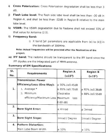
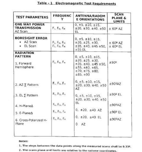
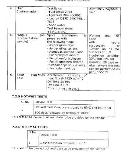
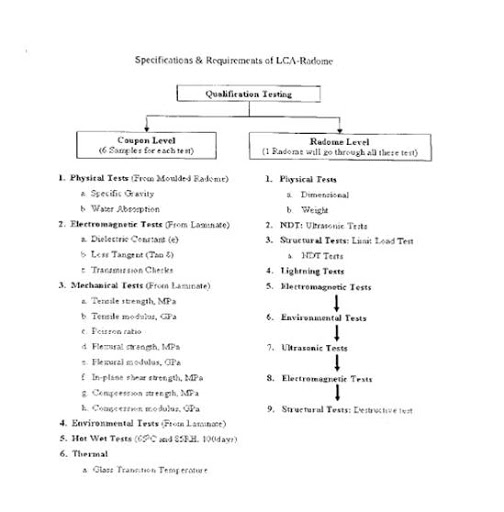
Set:4 - Testing parameters for new Radome


Re: Project BRF: Radome technology in India
Set:5 - Testing parameters for new Radome


Re: Project BRF: Radome technology in India
After Looking at that spec. I think Simulation would be just 5-10%. It wold be possible to simulate in silico EM, Vibration and thermal shocks, and a few other environmental test like fog and rain. Some idea can be gotten about the fungal growth, salt solution effects. Even simulation is a long drawn process for sure.
Re: Project BRF: Radome technology in India
Saw the hack (with distinct nose cone) flying over Sarjapur today, can anyone else confirm?
Re: Project BRF: Radome technology in India
^^^ Lots of test flying of the radome flying test bed going. At least 02/03 times per week.
Re: Project BRF: Radome technology in India
A few comments from ArunS:
1) An increase in 15% is about a gain of 1dB in the radome transmissivity
2) When the LCA goes through supersonic flight the skin temp could be high as 200deg C. At that temp the normal resin could soften and the Kevlar fibers move around.
3) Hence quartz with BMI is being changed for high temp capability.
Next the difficulty:
1) The radar antenna has rectangular modules all over the disc shape.
2) Now each element will experience different radome thickness based on the viewing angle. Eg. elements in the center will have less distortion than those at the edges. IOW its like looking through a fuzzy glass.
3) The radar processor has to integrate all these and come up with a clear image for the pilot.
4) The a2g mode will have even more difficulty due to slant angle of the cone.
All this requires time to iron out.
Looks like systems engineering of requirements was not good.
The radar and radome were in two silos and marched ahead till they came together in 2013 when they needed to get new radome.
Still a good learning experience.
My question:
Why not let the plane fly with the existing radome and change it out slowly?
Re: Project BRF: Radome technology in India
Another comment from Arun_S:
The problem appears to be the AESA radar in the LCA footprint does not have the required power for that weight.
The conical angle is too small for the radar to develop its full capability. It can with more power.
But would mean more weight.
The problem appears to be the AESA radar in the LCA footprint does not have the required power for that weight.
The conical angle is too small for the radar to develop its full capability. It can with more power.
But would mean more weight.
-
member_25400
- BRFite -Trainee
- Posts: 49
- Joined: 11 Aug 2016 06:14
Re: Project BRF: Radome technology in India
More power means more (waste) heat, which needs cooling. Which needs space and weight. Or it may impact reliability. Some airplanes can also be power limited.
Re: Project BRF: Radome technology in India
What is the available diameter for the AESA radar in the LCA nose area?