That is where the jet starter comes into the picture, a small gas turbine that spins the fan.Singha wrote:How does a jet engine start...how does the fan get spun initially to force air inside for combustion to start ?
Kaveri & Aero-Engine: News & Discussion
Re: Kaveri & aero-engine discussion
Re: Kaveri & aero-engine discussion
Thanks shiv, geeth, nachiket and maitya. Some information to chew on.
There is no other option than to fix the problems with the Kaveri discovered during flight trials in Russia and then get it onto the Tejas in 18 months to get critical flight experience with flying it in a fighter. Tejas can easily be powered with the existing Kaveri if it has no payload, or a very light payload. So no issues there. At the same time a parallel effort to design a follow on needs to be started. If the goal is to get it into AMCA then it needs to be sized to that from now on itself with some margin for the AMCA to be overweight.
Also get the Kaveri into the UCAV and get further experience from that vehicle.
-
negi
- BRF Oldie
- Posts: 13112
- Joined: 27 Jul 2006 17:51
- Location: Ban se dar nahin lagta , chootiyon se lagta hai .
Re: Kaveri & aero-engine discussion
In layman's terms when it comes to small size jet engines a turbojet engine is far more simpler to build and gives you required T:W ratio given the size constraints. The primary driver for introducing a bypass in a jet engine is for improving SFC , the modern military TF engines have a bypass ratio between 0.3-0.5 as there is no longer a requirement for these AC to go fly in excess of Mach 2.5+ most of them have top speeds ~Mach2 so they would rather have an engine that site somewhere between a pure turbojet and a HBP turbofan.merlin wrote: So the question is why have the low bypass ratio in the first place? Its not as if GTRE would be unaware of the pros and cons of various bypass ratios.
Again introducing a bypass comes at a cost of specific thrust and when operating in reheat mode an engine with a bypass will no longer enjoy the SFC advantage over a turbojet as latter has far higher pressure in it's reheat system.
Mig 29's RD33 has a bypass ratio of 0.49/1 and yet it's SFC is nothing great to talk about and it has to use 4 fan stages and 9 HPC stages to get a compression ratio of 21 moreover it's thrust and SFC numbers are very close to Kaveri despite being a much larger and heavier engine. Reason why brought up Rd33 is it does not use SCB and other exotic material , does not boast of those chi chi high compression ratio numbers like M88/Ej200 and it's TeT numbers are very SDRE about 1400-1500K again very much in line with Kaveri.
Last edited by negi on 17 Feb 2013 20:16, edited 3 times in total.
Re: Kaveri & aero-engine discussion
P&W exactly knew what Kaveri lacked (my take)... but they would not reveal in public, and our GTRE men does not like it too.
Re: Kaveri & aero-engine discussion
Russian trials revealed problems in LP
-
Varoon Shekhar
- BRF Oldie
- Posts: 2178
- Joined: 03 Jan 2010 23:26
Re: Kaveri & aero-engine discussion
"indigenous engine development activities undertaken in India in the mid 1960s. HJE-2500 was developed for basic jet trainer aircraft, HJT-16 MK 2."
Did this aircraft actually fly with the engine? If so, highly impressive for a third world country( more so back then) in the 1960s! How many flights, and when was it discarded?
Did this aircraft actually fly with the engine? If so, highly impressive for a third world country( more so back then) in the 1960s! How many flights, and when was it discarded?
Re: Kaveri & aero-engine discussion
This is totally wrong. Where is the quote taken from? The HJE 2500 was for the HF 24 and the engine never flew. There was also an Egyptian engine attempt for the HF 24 - a Helwan something or other that failed, Egypt has only gone down since thnVaroon Shekhar wrote:"indigenous engine development activities undertaken in India in the mid 1960s. HJE-2500 was developed for basic jet trainer aircraft, HJT-16 MK 2."
Re: Kaveri & aero-engine discussion
Info board here claims otherwise
http://upload.wikimedia.org/wikipedia/c ... m_7915.JPG
http://upload.wikimedia.org/wikipedia/c ... m_7915.JPG
Re: Kaveri & aero-engine discussion
I think the board may be wrong but am willing to have my qibla set right. I will cross check - but this is the first time I have ever read of an association between the HJT 16 and the HJE 2500Anujan wrote:Info board here claims otherwise
http://upload.wikimedia.org/wikipedia/c ... m_7915.JPG
Re: Kaveri & aero-engine discussion
Looks like I am wrong and the board must be right. There is no mention of HJE 2500 with HF 24shiv wrote:I think the board may be wrong but am willing to have my qibla set right. I will cross check - but this is the first time I have ever read of an association between the HJT 16 and the HJE 2500Anujan wrote:Info board here claims otherwise
http://upload.wikimedia.org/wikipedia/c ... m_7915.JPG
http://www.bharat-rakshak.com/IAF/Histo ... arut1.html
Re: Kaveri & aero-engine discussion
Singhaji in older days, when engines were jet engines were smaller (small dia) there were many schemes to start it. Electric start, cartridge start (our canberrars had cartridge starters). Problem with electric start is you need higher voltages to start a big engine. As the engines evolved into bigger and bigger size electric start was abandoned in favour of air starters.Singha wrote:How does a jet engine start...how does the fan get spun initially to force air inside for combustion to start ?
An air starter is a small turbine that is attatched to the jet engine via AMAGB. It is actually attatched to accessory gear box. This air starter is rotated by compressed air fed to the starter via big hose pipes. These are visible as thick hoses connecting the yellow starter cart to the aircraft. Starter carts/APU feed compressed air into the starter and the starter then rotates the high pressure spool aka core. Once the core fires up, the gas pressure exiting through the exahust end works on the low pressure turbine and the low pressure spool spins up slowly. It takes some time for it to stablize at it's idle rpm.
Cheers....
Re: Kaveri & aero-engine discussion
Yes, worst idea would be to throw the baby out with the bath water and stop developing the Kaveri further. Or stop developing newer versions or spinoffs or derivatives.Marten wrote:You know, Merlin, it's something a few senior scientists at GTRE agree with. Overweight or not, unless they get testbeds and real feedback, it's going to be difficult for them to also refine their designs/knowledge. Despite what everyone believes, I know at least a couple of these folks who gave up brilliant careers to come jumpstart various programs, and the failures do not deter them. They KNOW these are steps each country must take in order to advance. It is just that a large number of Indians have low self confidence and on the first pretext, will blame each other for what is perceived as failure. The ability to soak in these mis-steps and continuing to plan for success is not encouraged as often as it must be, at least in research.
-
negi
- BRF Oldie
- Posts: 13112
- Joined: 27 Jul 2006 17:51
- Location: Ban se dar nahin lagta , chootiyon se lagta hai .
Re: Kaveri & aero-engine discussion
Our problem is we don't take whatever product which we embark on to it's logical conclusion; spec wise Kaveri is better than a baseline RD33 (an engine which powers a pretty formidable AC ) and we have already started talking about some Kaveri-xx for powering the AMCA. So what if Kaveri powered LCA will be underpowered ? Is the burden of coming up with latest and greatest only on GTRE and DRDO combine ? When foreign stuff fails the top command says bah humbug "We will fight with what we have" , how about fighting with what we can make ? Back in the days when F-14 was powered by the P&W TF-30 engine which was not only underpowered but was notorious for throwing compressor blades they came up with a jugaad and build a steel cage to prevent the blades from destroying the engine; the USN persisted with this engine until GE F110 was available. So for a significant period of their service life F-14s operated with engines which had a T:W ratio less than 1. From the looks of it , it seems to me the kind of performance being expected out from Kaveri is in M88/F414/EJ200 class and this is supposed to be our first indigenous turbofan . If this is not what qualifies as setting oneself for failure then wonder what is. So what if baseline engine delivers just 50kN of thrust in dry and say 75kN of thrust in wet mode ? There is lot more to an engine than just thrust numbers; it needs to log hours in a production airframe to rule out issues like stalls/surges , collect data on key engine parameters like MTBF/MTBO and then work on whatever Kaveri-xx is required for AMCA.
Last edited by negi on 18 Feb 2013 21:49, edited 1 time in total.
Re: Kaveri & aero-engine discussion
by keeping the starting bar too high we are delaying fitting it on a plane and gathering valueable data and ideas how to make things rugged and reliable as a fielded product not a science proto touched only the elite scientists.
cheen makes no such mistake. good, bad or ugly it all goes in and flies.
cheen makes no such mistake. good, bad or ugly it all goes in and flies.
Re: Kaveri & aero-engine discussion
Very nice description thanks. I have learned something today.vikrant wrote:Singhaji in older days, when engines were jet engines were smaller (small dia) there were many schemes to start it. Electric start, cartridge start (our canberrars had cartridge starters). Problem with electric start is you need higher voltages to start a big engine. As the engines evolved into bigger and bigger size electric start was abandoned in favour of air starters.Singha wrote:How does a jet engine start...how does the fan get spun initially to force air inside for combustion to start ?
An air starter is a small turbine that is attatched to the jet engine via AMAGB. It is actually attatched to accessory gear box. This air starter is rotated by compressed air fed to the starter via big hose pipes. These are visible as thick hoses connecting the yellow starter cart to the aircraft. Starter carts/APU feed compressed air into the starter and the starter then rotates the high pressure spool aka core. Once the core fires up, the gas pressure exiting through the exahust end works on the low pressure turbine and the low pressure spool spins up slowly. It takes some time for it to stablize at it's idle rpm.
Cheers....
Re: Kaveri & aero-engine discussion
How is the engine restarted in the air , in case of a stall? - Thnxvikrant wrote:Singhaji in older days, when engines were jet engines were smaller (small dia) there were many schemes to start it. Electric start, cartridge start (our canberrars had cartridge starters). Problem with electric start is you need higher voltages to start a big engine. As the engines evolved into bigger and bigger size electric start was abandoned in favour of air starters.Singha wrote:How does a jet engine start...how does the fan get spun initially to force air inside for combustion to start ?
An air starter is a small turbine that is attatched to the jet engine via AMAGB. It is actually attatched to accessory gear box. This air starter is rotated by compressed air fed to the starter via big hose pipes. These are visible as thick hoses connecting the yellow starter cart to the aircraft. Starter carts/APU feed compressed air into the starter and the starter then rotates the high pressure spool aka core. Once the core fires up, the gas pressure exiting through the exahust end works on the low pressure turbine and the low pressure spool spins up slowly. It takes some time for it to stablize at it's idle rpm.
Cheers....
Re: Kaveri & aero-engine discussion
Small corrigendum
It should high current not high voltage
The starting torque require high current and hence huge cables
http://www.pilotfriend.com/aero_engines ... g_elec.htm
Restart is by pressing a button
I think there is enough of electrical supply through aux engine in the tail of the a/c and is usually started by electric starter in addition remember the air craft is in motion and the turbine is already revolving due to the air gushing in...
-
negi
- BRF Oldie
- Posts: 13112
- Joined: 27 Jul 2006 17:51
- Location: Ban se dar nahin lagta , chootiyon se lagta hai .
Re: Kaveri & aero-engine discussion
There is no need for a re-start per se as the Stall does not mean than compressor stages have completely come to a stand still . In case of modern engines FADEC takes care of most of such cases.
http://en.wikipedia.org/wiki/Compressor_stall
http://en.wikipedia.org/wiki/Compressor_stall
-
vina
- BRF Oldie
- Posts: 6046
- Joined: 11 May 2005 06:56
- Location: Doing Nijikaran, Udharikaran and Baazarikaran to Commies and Assorted Leftists
Re: Kaveri & aero-engine discussion
It is enough if just one engine is operational. The bleed air from the high pressure system is used to start the other engines in sequence. If both engines are out, the APU needs to start to be able to provide starting air and keep the hydraulics and electricals etc in operation.. Also planes lower a ram air turbine (basically a fancy name for a fan) that can generate emergency power . As a last resort , the plane will be attempt to windmill back to starting conditions, by dropping nose and going into a dive.How is the engine restarted in the air
That is why the APU is a critical safety component and has to be flight qualified up to the service ceiling for twin engines like the 777 etc.
Now you know why the "all electric" and bleed less planes like 787, the battery problem is so critical. Everything is electric driven.
For fighter jets, rather than an APU they use a JFS (the LCA does, it is a HAL designed piece that was qualified to operate at LEH). That JFS is coupled directly to the engine spool and brings it up to speed. The JSF itself is charged by a hydraulic accumulator , which gets charged in one or two revs of the engine once it starts. Also, the accumulator can be laboriously hand cranked on the ground to get it charged. A pretty reliable system that you can leave as is for months in some cases and still get a start.
Re: Kaveri & aero-engine discussion
It is for posts like those that I visit BR. Thanks for sharing, Mufti Vinatullah.
Re: Kaveri & aero-engine discussion
Thanks Shiv. Vina has summed it all up.
Cheers....
Cheers....
Re: Kaveri & aero-engine discussion
good post vina!
-
Varoon Shekhar
- BRF Oldie
- Posts: 2178
- Joined: 03 Jan 2010 23:26
Re: Kaveri & aero-engine discussion
Can anyone state whether the HJE-2500 was actually used/flown on a HJT-16, as opposed to merely being successfully tested on the ground?shiv wrote:shiv wrote: Looks like I am wrong and the board must be right. There is no mention of HJE 2500 with HF 24
http://www.bharat-rakshak.com/IAF/Histo ... arut1.html
Re: Kaveri & aero-engine discussion
As far as my knowledge goes, no Indian made engine has ever powered a manned aircraft before the recent Kaveri tests in Russia.Varoon Shekhar wrote:Can anyone state whether the HJE-2500 was actually used/flown on a HJT-16, as opposed to merely being successfully tested on the ground?shiv wrote: Looks like I am wrong and the board must be right. There is no mention of HJE 2500 with HF 24
http://www.bharat-rakshak.com/IAF/Histo ... arut1.html
Re: Kaveri & aero-engine discussion
Documentary on Rolls Royce - How To Build A Jumbo Jet Engine (Start @ 7.0 min)
This for the civilian engine but does bring out the complexities involved in building a modern jet engine.
This for the civilian engine but does bring out the complexities involved in building a modern jet engine.
Re: Kaveri & aero-engine discussion
[Part 1]
Continuing from my previous post of the SCB and Turbine blade Metallurgy related issues wrt Kaveri, here is another very humble attempt (in 2 parts) of moi, to explain in lay-man terms, of what seems to be the weakness in the Compressor part of the Kaveri/Kabini – which, I dare say, gets suppressed in the hullaballoo of SCB, TeT, BPR and what not.
Preamble: The hadiths, scattered as they were in various threads of BR, of the grand-mullah Enqyoobuddin Gas-turbini needs to completely internalized before any attempt of trying to understand the current Kaveri/Kabini imbroglio – so as per his (Piss BUH) sermon, the only thing that really matters to injiin performance are:
1. Highest possible pressure before heat addition in a combustor (aka OPR impact)
2. Highest possible temperature at end of heat addition post combustor (aka TeT impact)
Some such hadiths can be found here and here - and Vinaji's response to it here. Plus some more can be found here and here (and many other places – pls use the search feature of BR).
Before going on to ramble etc. let me just quote the grand-mullah Gas-turbini again, sermonizing that both are completely intrinsically linked to each other and any attempt to focus on one while ignoring the other simply doesn’t work.
The following schematic explains it succinctly:
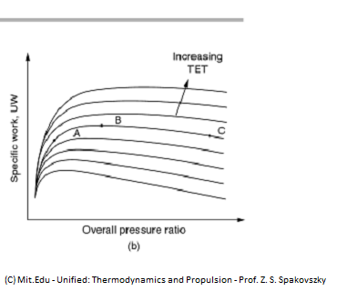
As it can be seen in the graph there’s almost an exponential growth in Thrust Values with increasing OPR, but it then plateaus out and starts falling-off – but this plateauing and falling-off can be postponed (and continue with the higher Thrust values) by suitably increasing the TeT.
(Disclaimer: Pls note TR is actually the ratio of TeT and Atmospheric temp, but since Atm Temp can be assumed constant for a particular altitude, the graph will similar if drawn against pure TeT also – and for simplicity sake, though tempting, let’s not bring in flat-rating etc discussion into this pls)[/
Now let’s examine the OPR impact part in a little more detail.
For a given core-mass flow (aka the energy available from the upstream turbines) the pressure ratio achieved before entering the combustor (and heat getting added there-in), is directly linked to (a) Overall Compressor Design and (b)Design/Manufacturing finesse of the compressor blades .
(a)Overall Compressor Design: There are 3 LP and 6 HP stages in Kabini – and it achieves 21-22 OPR, with these 9 stages, which translates to <1.4 Avg Stage Pressure Ratio (aka the pressure ratio achieved by each of these stages). Contrasted against a contemporary design goal of 30 OPR with 6-7 stages (say in 27atm of a F-414 or 35atm of a F-135), that can be achieved with 2.0 Avg stage Pressure Ratio.
So if the Kabini Compressor stages were to be magically (by “jiiinn” tech © grand-mullah Gas-turbini-enqyoobuddin) made efficient enough to nudge the perf towards a 27-30 OPR values (aka increase in the SPR values trending towards a 1.9-2.0), it will either help in increasing the thrust levels (both dry and wet) or if the designers choose to maintain the current thrust levels, they can do the reduction of compressor stages and reduce weight (Kaveri is 150Kg overweight, IIRC).
IOW, a contemporary design of 30OPR achievement by 6-7 stage-compressor design would have meant Kaveri with a reduced weight, still meeting the design thrust-weight ratio quite handsomely, at the current design thrust levels.
Conversely, keeping the same 9 (3 LP + 6 HP) stage core-design, if these stages were to be somehow made efficient enough to attain a contemporary STR in the region of 1.9-2.0, the resultant thrust-levels attained would be higher than the design level but due to the current exceeding-weight levels, again attaining the ballpark thrust-to-weight ratio.
Disclaimer 1: Both the above calc are very rudimentary, assuming a similar PR achievement for each of these compressor stages, which in practice wouldn’t be the case, and would be non-linear – so while a straight calc would have given a result of 5 stages, but given the non-linearity etc, I safely choose 2 more stages to mitigate it.
Disclaimer 2: This “theoretical” 2 stage reduction is a bit interesting. Since, say instead of trying to reduce the HPC stages alone, if an attempt is made for reducing 1 from LPC and 1 from HPC (as LPC stages are generally more heavier than the HPC ones), it will create another issue as there are a certain minm number of LPC stages required to “shape” the flow before it hits the HPC stages to make it perform optimally to generate the required OPR – need to think this thru.
Disclaimer 3: Increasing the OPR blindly, without similar calibrated increase in TeT and combustor design, may actually downgrade the work-extraction (aka thrust-levels, refer to the graph above) levels – but that point discussion, a little later.
But none of these happens in Kaveri and it continues to struggles along with a 1.4 SPR, not because the GTRE folks didn’t aim for it (they actually aimed for a SPR of 1.6 with 88% isentropic efficiency), but more because there were deficiency in the compressor blade design and manufacturing finesse part (detailed in Part 2).
(contd...)
Continuing from my previous post of the SCB and Turbine blade Metallurgy related issues wrt Kaveri, here is another very humble attempt (in 2 parts) of moi, to explain in lay-man terms, of what seems to be the weakness in the Compressor part of the Kaveri/Kabini – which, I dare say, gets suppressed in the hullaballoo of SCB, TeT, BPR and what not.
Preamble: The hadiths, scattered as they were in various threads of BR, of the grand-mullah Enqyoobuddin Gas-turbini needs to completely internalized before any attempt of trying to understand the current Kaveri/Kabini imbroglio – so as per his (Piss BUH) sermon, the only thing that really matters to injiin performance are:
1. Highest possible pressure before heat addition in a combustor (aka OPR impact)
2. Highest possible temperature at end of heat addition post combustor (aka TeT impact)
Some such hadiths can be found here and here - and Vinaji's response to it here. Plus some more can be found here and here (and many other places – pls use the search feature of BR).
Before going on to ramble etc. let me just quote the grand-mullah Gas-turbini again, sermonizing that both are completely intrinsically linked to each other and any attempt to focus on one while ignoring the other simply doesn’t work.
The following schematic explains it succinctly:
As it can be seen in the graph there’s almost an exponential growth in Thrust Values with increasing OPR, but it then plateaus out and starts falling-off – but this plateauing and falling-off can be postponed (and continue with the higher Thrust values) by suitably increasing the TeT.
(Disclaimer: Pls note TR is actually the ratio of TeT and Atmospheric temp, but since Atm Temp can be assumed constant for a particular altitude, the graph will similar if drawn against pure TeT also – and for simplicity sake, though tempting, let’s not bring in flat-rating etc discussion into this pls)[/
Now let’s examine the OPR impact part in a little more detail.
For a given core-mass flow (aka the energy available from the upstream turbines) the pressure ratio achieved before entering the combustor (and heat getting added there-in), is directly linked to (a) Overall Compressor Design and (b)Design/Manufacturing finesse of the compressor blades .
(a)Overall Compressor Design: There are 3 LP and 6 HP stages in Kabini – and it achieves 21-22 OPR, with these 9 stages, which translates to <1.4 Avg Stage Pressure Ratio (aka the pressure ratio achieved by each of these stages). Contrasted against a contemporary design goal of 30 OPR with 6-7 stages (say in 27atm of a F-414 or 35atm of a F-135), that can be achieved with 2.0 Avg stage Pressure Ratio.
So if the Kabini Compressor stages were to be magically (by “jiiinn” tech © grand-mullah Gas-turbini-enqyoobuddin) made efficient enough to nudge the perf towards a 27-30 OPR values (aka increase in the SPR values trending towards a 1.9-2.0), it will either help in increasing the thrust levels (both dry and wet) or if the designers choose to maintain the current thrust levels, they can do the reduction of compressor stages and reduce weight (Kaveri is 150Kg overweight, IIRC).
IOW, a contemporary design of 30OPR achievement by 6-7 stage-compressor design would have meant Kaveri with a reduced weight, still meeting the design thrust-weight ratio quite handsomely, at the current design thrust levels.
Conversely, keeping the same 9 (3 LP + 6 HP) stage core-design, if these stages were to be somehow made efficient enough to attain a contemporary STR in the region of 1.9-2.0, the resultant thrust-levels attained would be higher than the design level but due to the current exceeding-weight levels, again attaining the ballpark thrust-to-weight ratio.
Disclaimer 1: Both the above calc are very rudimentary, assuming a similar PR achievement for each of these compressor stages, which in practice wouldn’t be the case, and would be non-linear – so while a straight calc would have given a result of 5 stages, but given the non-linearity etc, I safely choose 2 more stages to mitigate it.
Disclaimer 2: This “theoretical” 2 stage reduction is a bit interesting. Since, say instead of trying to reduce the HPC stages alone, if an attempt is made for reducing 1 from LPC and 1 from HPC (as LPC stages are generally more heavier than the HPC ones), it will create another issue as there are a certain minm number of LPC stages required to “shape” the flow before it hits the HPC stages to make it perform optimally to generate the required OPR – need to think this thru.
Disclaimer 3: Increasing the OPR blindly, without similar calibrated increase in TeT and combustor design, may actually downgrade the work-extraction (aka thrust-levels, refer to the graph above) levels – but that point discussion, a little later.
But none of these happens in Kaveri and it continues to struggles along with a 1.4 SPR, not because the GTRE folks didn’t aim for it (they actually aimed for a SPR of 1.6 with 88% isentropic efficiency), but more because there were deficiency in the compressor blade design and manufacturing finesse part (detailed in Part 2).
(contd...)
Re: Kaveri & aero-engine discussion
[Part 2]
(b) Compressor Blade Design/Manufacturing aspects: This brings out the other elephant in the room – design and manufacturing aspects of the compressor stages.
Now, if we look back at the history of compressor stage evolution, there are mainly 3 generations:
1st Gen, Subsonic Level – Achieved in the 1960s, the multi-stage compressor with tip Mach numbers < 0.8, with limited achievable compression ratios to about 17.
2nd Gen, Basic Transonic Level – Achieved towards end of 70s (and early 80s), with tip Mach numbers between 1.0 and 1.1, achieving SPRs of around 1.4-1.5. These were also characterized by slight improvement in blade aspect ratio and double circular arc-profile blade designs (more on this aspect a little later). The avg temp rise per stage also doubled (from 21K to 42K, per stage) due to this increase in blade speed, and thus required improvement in compressor blade metallurgy. Most probably Kaveri compressors are of this gen.
3rd Gen, Adv Transonic Level with wide-chord blade design – Achieved towards end of 80s (and early 90s), with tip Mach numbers trending towards 1.6, achieving SPRs of around 2.0. But the definitive characteristic of this generation is a wide chord blade design (with blade aspect ratios around 1) and multi circular arc-profile blade designs. Here again further improvement in compressor blade metallurgy is required as the the avg temp rise per stage went up to 65-75K. It’s claimed that the compressors of the EJ200, F119 etc (with OPR of 30 achieved in only 6-7 stages) are of this gen.
So, as it can be seen in the above classification, talking about the compressor blade design (and manufacturing) aspects towards improving the efficiency (and the SPR) hinges on the following 4 basic dimension :
1) Compressor Blade Speed
2) Basic Blade Design towards low aspect ratio (wider chord design) – helps in superior aerodynamics in handling the flow between the blades and the side walls and also in the reduced axial pressure gradient along the side walls
3) Blade Geometry– From conventional subsonic aero-foil design to a double circular arc profile to multi-circular arc profile
4) Compressor blade Strength and Blade Loading – to handle higher speed and rise in operating temp
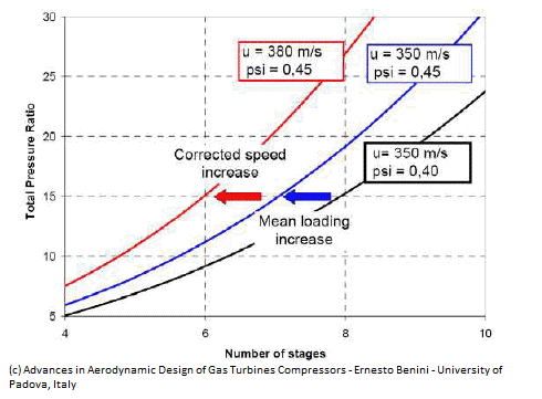
So let’s look at more closely at how each of these factors impacts the SPR (so eventually OPR as well). Pls refer to the following schematic:
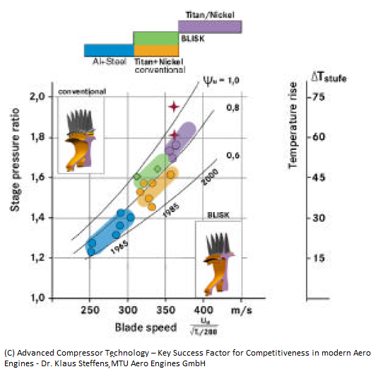
1 and 2) Effect of Blade Speed and Blade Aspect Ratio: Not only does the above schematic amply demonstrate that the Stage Pressure Ratio can be increased by increasing the blade-speed but it also depicts that the rate of SPR increase (from the gradient comparison of the graphs) goes up quite significantly with the increase in an another parameter called Work Co-efficient. Furthermore, it also depicts that a blade speed of around the 400m/s (approx. 1.3Mach) combined with a Work Coefficient of 0.8-1.0 ensures the SPR value gets upto the 1.9-2.0 mark.
But this Work Co-efficient of the blades is dependent on the Aspect Ratio of the compressor blades – pls refer to the following schematic again:
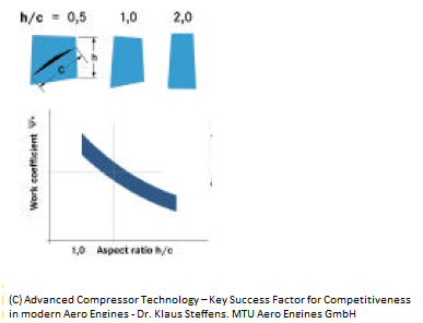
As it can be clearly seen with the reduction of the blade aspect ratio the work co-efficient increases which, for a given blade speed, helps increasing the SPR (and thus the OPR as well) (refer to the previous graph as well).
So far so good i.e. the SPR (and thus the OPR, as well) of a compressor can be increased by having low-aspect ratio (aka wide chord) blades and by somehow moving towards a higher blade speed (i.e. from a subsonic to transonic to high transonic levels).
3) Effect of Blade Geometry: But an interesting problem happens while trying to increase the blade speed to the transonic levels – the blade geometry starts playing spoilsport. A conventional highly cambered subsonic aerofoil blade design with high suction surface curvature started producing unacceptably high shock losses and a rapid fall off in SPR.
Furthermore this gets compounded with further spaced co-axial blade stages (a term called solidity – ratio of the blade chord length and distance between the concentric blades, in the same line).
So this was resolved with different blade aerofoil design of first the double circular arc profile and then to multi-circular arc profile – plus by spacing the compressor stages optimally the solidity was also increased in conjunction with this. Pls refer to the schematic below:
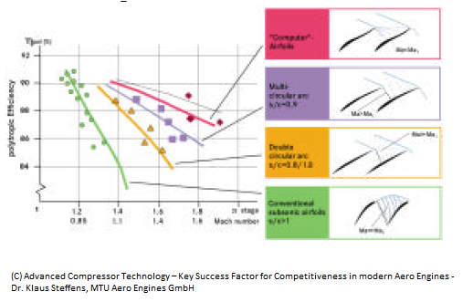
As it can be seen with the decrease in suction surface curvature brought about by the introduction of double circular (yellow graph) and multi circular blade (violet graph) profile designs, the efficiency fall can be arrested quite dramatically upto certain transonic blade speeds (before the fall becomes too steep) for e.g. Notice the diff in efficiency levels at 1.3M between subsonic aero-foil design, double circular arc profile design and a multi-circular arc profile design.
It is reported that there are certain multi circular blade aerofoil designs with zero-curvature (further limiting the supersonic expansion ahead of the shock and hence the shock intensity and the inherent losses) on the suction surface allowing blade-speeds to go upto M1.6.
4) Compressor blade Strength and Blade Loading: Increasing blade tip speeds and lower aspect ratio blades comes with a resultant increase in centrifugal force implying mechanical stress (quite a bit) on the blade root and blade-disc fixtures. Furthermore increasing the blade tip speed etc will result in stage temperature increase as well (as shown in the graph at the top). Also low-aspect ratio blades will have addn issues of plate vibrations which can not only create critical blade resonances but also have potential coupling of vibrational excitations over several stages.
(ps: IIRC, Kaveri had to deal with 3rd order resonance issues which got identified only when it got tested in Germany at a very late stage, I think – not sure).
All of this requires addn blade strength and enhanced temp tolerance – pls refer to the following schematic to the impact on compressor blade loading, blade speed, OPR and number or compressor stages – which basically means higher the blade strength, more blade speed it can accommodate, increasing the OPR but thru lesser number of stages.
This then brings firmly into the territory of blisk manufacturing, higher thermal loading metallurgy, High speed milling, Electro-Chemical machining, Linear friction welding etc. etc.
Epilogue: So what does all this mean wrt Kaveri/Kabini?
To increase the OPR from a 21-22 to a more contemporary 27-30 OPR would require progress on several cutting edge compressor technologies as well as improvement in TeT etc – and, more importantly, the compressor shortcomings shouldn’t get overshadowed by the incessant wailing about BPR, SCB and low TeT etc (though equally, if not more, important and inherently linked aspects, no doubt).
The compressor level improvement in Kaveri/Kabini required, IMVVHO, are as follows:
1) Graduating to a high transonic blade speed regime of say 1.5-1.6M
2) Low aspect ratio (aka wide chord) blade design and manufacturing
3) Manufacturing (mass-level) capability of multi-circular arc profile compressor blades (just drawing a design of it on a paper wouldn’t do)
4) To cater to the above three developing/acquiring manufacturing capability of increased blade strength and loading – by usage of blisk manufacturing, higher thermal loading metallurgy, High speed milling, Electro-Chemical machining, Linear friction welding etc. etc.
And last but not the least have proper CeeFDee capability on 3-D NS Flows and other such good and exotic stuff – to test and analyse compressors down to detailed inter-stage data out of the rotating system in order to understand the aerodynamic and vibrational behaviors.
Essentially, as the grand-mullah Enqyoobuddin Gas-turbini had sermoned many moons back, get hordes of DOO and PIGS onto this with freedom of destroying a couple of cores, with harsh timelines and supervision and see the results – PissBUH!!
(b) Compressor Blade Design/Manufacturing aspects: This brings out the other elephant in the room – design and manufacturing aspects of the compressor stages.
Now, if we look back at the history of compressor stage evolution, there are mainly 3 generations:
1st Gen, Subsonic Level – Achieved in the 1960s, the multi-stage compressor with tip Mach numbers < 0.8, with limited achievable compression ratios to about 17.
2nd Gen, Basic Transonic Level – Achieved towards end of 70s (and early 80s), with tip Mach numbers between 1.0 and 1.1, achieving SPRs of around 1.4-1.5. These were also characterized by slight improvement in blade aspect ratio and double circular arc-profile blade designs (more on this aspect a little later). The avg temp rise per stage also doubled (from 21K to 42K, per stage) due to this increase in blade speed, and thus required improvement in compressor blade metallurgy. Most probably Kaveri compressors are of this gen.
3rd Gen, Adv Transonic Level with wide-chord blade design – Achieved towards end of 80s (and early 90s), with tip Mach numbers trending towards 1.6, achieving SPRs of around 2.0. But the definitive characteristic of this generation is a wide chord blade design (with blade aspect ratios around 1) and multi circular arc-profile blade designs. Here again further improvement in compressor blade metallurgy is required as the the avg temp rise per stage went up to 65-75K. It’s claimed that the compressors of the EJ200, F119 etc (with OPR of 30 achieved in only 6-7 stages) are of this gen.
So, as it can be seen in the above classification, talking about the compressor blade design (and manufacturing) aspects towards improving the efficiency (and the SPR) hinges on the following 4 basic dimension :
1) Compressor Blade Speed
2) Basic Blade Design towards low aspect ratio (wider chord design) – helps in superior aerodynamics in handling the flow between the blades and the side walls and also in the reduced axial pressure gradient along the side walls
3) Blade Geometry– From conventional subsonic aero-foil design to a double circular arc profile to multi-circular arc profile
4) Compressor blade Strength and Blade Loading – to handle higher speed and rise in operating temp
So let’s look at more closely at how each of these factors impacts the SPR (so eventually OPR as well). Pls refer to the following schematic:
1 and 2) Effect of Blade Speed and Blade Aspect Ratio: Not only does the above schematic amply demonstrate that the Stage Pressure Ratio can be increased by increasing the blade-speed but it also depicts that the rate of SPR increase (from the gradient comparison of the graphs) goes up quite significantly with the increase in an another parameter called Work Co-efficient. Furthermore, it also depicts that a blade speed of around the 400m/s (approx. 1.3Mach) combined with a Work Coefficient of 0.8-1.0 ensures the SPR value gets upto the 1.9-2.0 mark.
But this Work Co-efficient of the blades is dependent on the Aspect Ratio of the compressor blades – pls refer to the following schematic again:
As it can be clearly seen with the reduction of the blade aspect ratio the work co-efficient increases which, for a given blade speed, helps increasing the SPR (and thus the OPR as well) (refer to the previous graph as well).
So far so good i.e. the SPR (and thus the OPR, as well) of a compressor can be increased by having low-aspect ratio (aka wide chord) blades and by somehow moving towards a higher blade speed (i.e. from a subsonic to transonic to high transonic levels).
3) Effect of Blade Geometry: But an interesting problem happens while trying to increase the blade speed to the transonic levels – the blade geometry starts playing spoilsport. A conventional highly cambered subsonic aerofoil blade design with high suction surface curvature started producing unacceptably high shock losses and a rapid fall off in SPR.
Furthermore this gets compounded with further spaced co-axial blade stages (a term called solidity – ratio of the blade chord length and distance between the concentric blades, in the same line).
So this was resolved with different blade aerofoil design of first the double circular arc profile and then to multi-circular arc profile – plus by spacing the compressor stages optimally the solidity was also increased in conjunction with this. Pls refer to the schematic below:
As it can be seen with the decrease in suction surface curvature brought about by the introduction of double circular (yellow graph) and multi circular blade (violet graph) profile designs, the efficiency fall can be arrested quite dramatically upto certain transonic blade speeds (before the fall becomes too steep) for e.g. Notice the diff in efficiency levels at 1.3M between subsonic aero-foil design, double circular arc profile design and a multi-circular arc profile design.
It is reported that there are certain multi circular blade aerofoil designs with zero-curvature (further limiting the supersonic expansion ahead of the shock and hence the shock intensity and the inherent losses) on the suction surface allowing blade-speeds to go upto M1.6.
4) Compressor blade Strength and Blade Loading: Increasing blade tip speeds and lower aspect ratio blades comes with a resultant increase in centrifugal force implying mechanical stress (quite a bit) on the blade root and blade-disc fixtures. Furthermore increasing the blade tip speed etc will result in stage temperature increase as well (as shown in the graph at the top). Also low-aspect ratio blades will have addn issues of plate vibrations which can not only create critical blade resonances but also have potential coupling of vibrational excitations over several stages.
(ps: IIRC, Kaveri had to deal with 3rd order resonance issues which got identified only when it got tested in Germany at a very late stage, I think – not sure).
All of this requires addn blade strength and enhanced temp tolerance – pls refer to the following schematic to the impact on compressor blade loading, blade speed, OPR and number or compressor stages – which basically means higher the blade strength, more blade speed it can accommodate, increasing the OPR but thru lesser number of stages.
This then brings firmly into the territory of blisk manufacturing, higher thermal loading metallurgy, High speed milling, Electro-Chemical machining, Linear friction welding etc. etc.
Epilogue: So what does all this mean wrt Kaveri/Kabini?
To increase the OPR from a 21-22 to a more contemporary 27-30 OPR would require progress on several cutting edge compressor technologies as well as improvement in TeT etc – and, more importantly, the compressor shortcomings shouldn’t get overshadowed by the incessant wailing about BPR, SCB and low TeT etc (though equally, if not more, important and inherently linked aspects, no doubt).
The compressor level improvement in Kaveri/Kabini required, IMVVHO, are as follows:
1) Graduating to a high transonic blade speed regime of say 1.5-1.6M
2) Low aspect ratio (aka wide chord) blade design and manufacturing
3) Manufacturing (mass-level) capability of multi-circular arc profile compressor blades (just drawing a design of it on a paper wouldn’t do)
4) To cater to the above three developing/acquiring manufacturing capability of increased blade strength and loading – by usage of blisk manufacturing, higher thermal loading metallurgy, High speed milling, Electro-Chemical machining, Linear friction welding etc. etc.
And last but not the least have proper CeeFDee capability on 3-D NS Flows and other such good and exotic stuff – to test and analyse compressors down to detailed inter-stage data out of the rotating system in order to understand the aerodynamic and vibrational behaviors.
Essentially, as the grand-mullah Enqyoobuddin Gas-turbini had sermoned many moons back, get hordes of DOO and PIGS onto this with freedom of destroying a couple of cores, with harsh timelines and supervision and see the results – PissBUH!!
Re: Kaveri & aero-engine discussion
Thank you maitya saar. One more question after going through the refererred publications by enqyoob et al. - how does the lower-than-should-be bypass ratio fit into this ? Is that an attempt to increase the pressure ratio, because the compressor isn't efficient enough ?
-
vina
- BRF Oldie
- Posts: 6046
- Joined: 11 May 2005 06:56
- Location: Doing Nijikaran, Udharikaran and Baazarikaran to Commies and Assorted Leftists
Re: Kaveri & aero-engine discussion
One advantage of having a totalitarian system like the Soviet Union or the PRC is the kind of things you can do, which you simply cannot do in a democratic society.
For eg .. Crunch this news.. China Nears Approval for a $16BILLION aero engine plan
The number is mind boggling, esp given that they are throwing it into basic R&D in materials, designs, test equipment etc.
And to think that the SDRES wanted to develop a Kaveri class engine for a grand total of Rs 300 crore (approx $60 MILLION). Okay. Even if they spend a grand total of Rs5000 crore over the Kaveri over 25 years (ie $1b) , it is ultra cheap!
Somehow, i will bet that between a Kaveri and a Kun Lun or Lun-Lun or WS-10 or Ws-13 or whatever is supposed to fly on the "Joint" Fighter 17 or the J-10/J-11 kind of ding dong, I am willing to bet on the Kaveri. We atleast have an engine flying, the materials falling in place and experience under our belt from designing our own stuff, rather than try to photo copy and AL-31 or the core of a CFM56
Re: Kaveri & aero-engine discussion
Deleted
Last edited by Suraj on 28 Feb 2013 22:47, edited 1 time in total.
Reason: Poster warned for trolling and thread disruption.
Reason: Poster warned for trolling and thread disruption.
-
negi
- BRF Oldie
- Posts: 13112
- Joined: 27 Jul 2006 17:51
- Location: Ban se dar nahin lagta , chootiyon se lagta hai .
Re: Kaveri & aero-engine discussion
Well key thing is engine design specs aim for EJ200 or M88 level performance . 
-
P Chitkara
- BRFite
- Posts: 355
- Joined: 30 Aug 2004 08:09
Re: Kaveri & aero-engine discussion
OT-Alert:
What would one interpret from that article? Their current program has failed to yield results?
This is HUGE amount of $$s. it will be interesting to see how do they develop new engines this time. Will it be the xerox route or grounds up development, only time will tell.
Coming back to the topic, is there any news on desi engine development for AMCA?
Re: Kaveri & aero-engine discussion
no it is not OT imho.. we don't care about their methods copy or straight from the books. the fact is the plan is out and open. it is a shame that we have no open support for Kaveri yet.
Re: Kaveri & aero-engine discussion
srin, on a slightly different but relevant note, pls appreciate that the problem of trying to analyze/explain turbojet workings strictly from a lay-man pov, is this dependence on rudimentary mathematical aspects to explain away complicated, multi-disciplinary high-funda stuff that includes exotic CeeFDee concepts like 3D NS, Boltzman Equations, Supersonic Shock Propagation, Boundary Value conditions of flow etc etc.srin wrote:Thank you maitya saar. One more question ... ?
But being a certified DOO, the method of overcoming it that appealed to me most, was to create a simple excel with the basic gas turbine parameters deriving other dependent parameters, from the 1st principles and then use these derivations and results for analysing/explaining generic gas-turbine queries/concepts/issues.
Agreed it’s over-simplified (e.g. Wcmpr = Wtrbn
Plus of course, this allows people to play around with various permutation-combination of the 3 basic turbojet parameters (viz. OPR, TET and Mass Flow) and start deriving and designing their own “paper-turbojets”.
So here goes:
PS: Some Pir-review will be extremely welcome.
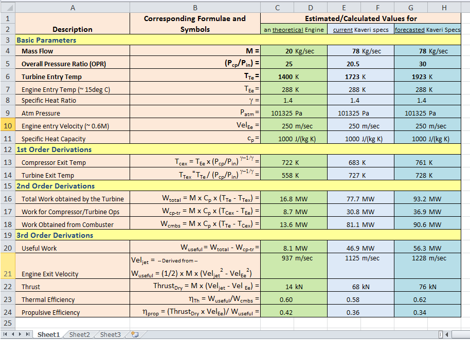
The method I’ve used is,
1. to first take only 3 input very basic variables (viz OPR, TeT and Mass Flow values)
2. plonk it along with other constants viz. Engine Entry Temp, Specific Heat Ratio (for a constant gas mass and volume), Atm Pressure of the engine operating scenario, Velocity of Air Intake and Specific Heat Capacity.
3. Using these, derive other basic gas-turbine parameters (depicted as 1st Level, 2nd Level and 3rd Level derivations)
4. Use the calculation/derivation process to explain away, from lay-man pov, the interplay between various turbo-jet concepts.
Here-in I’d like to also mention that the,
1. Green column was more towards validating the concepts/formulas used here-in, by comparing against published calc results for a certain set of the input variable values
2. Lighter blue column is to then use these baselined calcs (and assumptions) and play-around with the open-source (read Wiki) Kaveri parameters
3. Darker Blue is to do the above (like the lighter blue column) but with the aspirational parameters of Kaveri and see where these calcs go.
With this tool in place, I can now attempt to analyse/explain some of the turbo-jet idiosyncrasies and hopefully able to arrive at some conclusions - but that for some other day.
PS: Can somebody help this html-challenged-foggy how to type superscript/subscript and symbol laden formulaes in the forum posting software?
Re: Kaveri & aero-engine discussion
do we really know the boundary values for kaveri? would not that entirely depends on the design. anyway, the intended design in theory should point to different sets of boundaries as against achieved results. so, one can't change the boundary since the resultant product was de-rated.
we laymen are not interested in the ranges, except the boundary value that should match requirements. now, one may argue that IAF kept changing it, but that came at a new phase request and has real reasons to ignore and continue to support the program to achieve the expected results. that fact is not evident with GTRE thus far, nor was explicitly conveyed.
Now, we have a new charter without solving earlier boundaries [at least in jingo minds].
Re: Kaveri & aero-engine discussion
Needed to ^up this thread, so a quick post on the SCB Gens wouldn't harm, I guess!! 
Pls refer to this post of moi a couple of pages back ...
But pls do note, graduating from 2nd Gen (3% of Re) to 3rd Gen (5-6%) SCB metallurgy tech, a major hurdle needed overcoming - what happened was at Re levels around 5% (w/w) or more the solid solubility limit (wrt the matrix of Re crystal structure) was exceeded. Which meant that if such a blade is operated in high-temperature environments for prolonged duration, the excess Re levels may combine with other elements, reducing creep strength (pls note all this effort of increasing Re content was to increase creep strength in the first place).
Note: This is called as Topologically Close-Packed (TCP) Phase where-in you have close-packed atoms in layers separated by relatively large interatomic distances caused by sandwiched (between these layers) larger atoms. These plate-like structures negatively affects mechanical properties (ductility and creep-rupture) and are damaging for two reasons:
i) they tie up Gamma and Gamma-prime strengthening elements in a non-useful form, thus reducing creep strength
ii) they can act as crack initiators because of their brittle nature.
This was resolved by introducing Ru (that controls the TCP phase) to the Ni-based single crystal superalloy and adjusting the composition ratios of other component elements are set to optimal ranges so as to provide the optimal lattice constant of the matrix (γ phase) and the optimal lattice constant of the precipitate (γ' phase).
The 4th and 5th Gen SCBs are thus characterized not only by higher 8-9% (w/w) of Re levels but also gradually increasing % of Ru as well (4th Gen 3% Ru and 5th Gen with 4% Ru w/w).
But that's not all.
This continuous adding of a heavy metal like Re meant (worsened by presence of another heavy element W) a higher specific gravity (g/cm3) of the overall alloy goes up, increasing weight of the blade (and thus the engine as well). This was overcome by reducing the W composition percentage to 1.5-2% (from a level of about 5-6%). So basically increase in Re % in the composition was balanced (not linearly though) by corresponding reduction of the W.
And the reasearch continuous...
But I guess the bigger question is, where do we stand wrt indigenous mass-manufacture level of turbine blades (so complex geometry etc) with these various Gens of SCB technology.
Pls refer to this post of moi a couple of pages back ...
Continuing with the discussion on various gens of SCB etc, pls note that the world didn't really stop at Gen 3 (circa 2000) or thereabouts. Today the talk is about Gen 4 and 5 level SCB where the Re composition (w/w %) is in the realms of 8% to 9%.maitya wrote:Various SC Gens:
1st Gen SCBs:
...
...
2nd and 3rd Gen SCBs:
This is where open-source information starts becoming scanty – but these are characterized by degree of Rhenium (one of the rarest elements with third-highest melting point and highest boiling point) mixture in the alloy itself with 2nd Gen (CMSX-4) amounting to 3% (w/w) and for 3rd Gen (CMSX-10) to approx. >6% or so.
...
...
But pls do note, graduating from 2nd Gen (3% of Re) to 3rd Gen (5-6%) SCB metallurgy tech, a major hurdle needed overcoming - what happened was at Re levels around 5% (w/w) or more the solid solubility limit (wrt the matrix of Re crystal structure) was exceeded. Which meant that if such a blade is operated in high-temperature environments for prolonged duration, the excess Re levels may combine with other elements, reducing creep strength (pls note all this effort of increasing Re content was to increase creep strength in the first place).
Note: This is called as Topologically Close-Packed (TCP) Phase where-in you have close-packed atoms in layers separated by relatively large interatomic distances caused by sandwiched (between these layers) larger atoms. These plate-like structures negatively affects mechanical properties (ductility and creep-rupture) and are damaging for two reasons:
i) they tie up Gamma and Gamma-prime strengthening elements in a non-useful form, thus reducing creep strength
ii) they can act as crack initiators because of their brittle nature.
This was resolved by introducing Ru (that controls the TCP phase) to the Ni-based single crystal superalloy and adjusting the composition ratios of other component elements are set to optimal ranges so as to provide the optimal lattice constant of the matrix (γ phase) and the optimal lattice constant of the precipitate (γ' phase).
The 4th and 5th Gen SCBs are thus characterized not only by higher 8-9% (w/w) of Re levels but also gradually increasing % of Ru as well (4th Gen 3% Ru and 5th Gen with 4% Ru w/w).
But that's not all.
This continuous adding of a heavy metal like Re meant (worsened by presence of another heavy element W) a higher specific gravity (g/cm3) of the overall alloy goes up, increasing weight of the blade (and thus the engine as well). This was overcome by reducing the W composition percentage to 1.5-2% (from a level of about 5-6%). So basically increase in Re % in the composition was balanced (not linearly though) by corresponding reduction of the W.
And the reasearch continuous...
But I guess the bigger question is, where do we stand wrt indigenous mass-manufacture level of turbine blades (so complex geometry etc) with these various Gens of SCB technology.
Re: Kaveri & aero-engine discussion
It went to Gen 6 and further as we talk!Today the talk is about Gen 4 and 5 level SCB where the Re composition (w/w %) is in the realms of 8% to 9%.
While a metallurgist bristle himself to talk about phases, a material guy beams back to say after all those little dances your so called 'Single-Crystal' has to ride on the theme of Composites to gain its unwavering strength!Note: This is called as Topologically Close-Packed (TCP) Phase where-in you have close-packed atoms in layers separated by relatively large interatomic distances caused by sandwiched (between these layers) larger atoms. These plate-like structures negatively affects mechanical properties (ductility and creep-rupture) and are damaging for two reasons:
i) they tie up Gamma and Gamma-prime strengthening elements in a non-useful form, thus reducing creep strength
ii) they can act as crack initiators because of their brittle nature.
Sirji, I welcomed your attempt to put things in laymen terms. Don't know how challenging it will be do so the above para! I wish things were as simple as in those days.This was resolved by introducing Ru (that controls the TCP phase) to the Ni-based single crystal superalloy and adjusting the composition ratios of other component elements are set to optimal ranges so as to provide the optimal lattice constant of the matrix (γ phase) and the optimal lattice constant of the precipitate (γ' phase).
The 4th and 5th Gen SCBs are thus characterized not only by higher 8-9% (w/w) of Re levels but also gradually increasing % of Ru as well (4th Gen 3% Ru and 5th Gen with 4% Ru w/w).
Re: Kaveri & aero-engine discussion
Q: If blades can be so designed that it can sandwich heat exchange plates (some refractory metal alloy and good heat conductor/radiator) that are blisked to the center rotating core having an hollow design to let cool air from inlets.. and then the hot air exists via the exhaust after combustion chamber. can't such measure be taken in addition to coating technology?
Re: Kaveri & aero-engine discussion
Anyway, Kansonji you got me there ... from whatever little I know, things are absolutely not as simple as I tried to make it look like trying to describe it in lay-man terms.Kanson wrote:Sirji, I welcomed your attempt to put things in laymen terms. Don't know how challenging it will be do so the above para! I wish things were as simple as in those days.maitya wrote:This was resolved by introducing Ru (that controls the TCP phase) to the Ni-based single crystal superalloy and adjusting the composition ratios of other component elements are set to optimal ranges so as to provide the optimal lattice constant of the matrix (γ phase) and the optimal lattice constant of the precipitate (γ' phase).
The 4th and 5th Gen SCBs are thus characterized not only by higher 8-9% (w/w) of Re levels but also gradually increasing % of Ru as well (4th Gen 3% Ru and 5th Gen with 4% Ru w/w).
At a high level, each of these constituents contribute positively on quite narrow percentage composition levels - things starts unravelling no sooner these boundaries are breached, and most of the times, they start undercutting the very same properties they were supposed to boost in the first place. The example, that I'd quoted in my previous post, exemplefies this very fact for Rhenium.
Re: Kaveri & aero-engine discussion
CROSS POST:
Unrelated to missiles, but related to aeroengines. I don't know what is the intended use of HAL's 20kN turbofan engine.
1. Turbofan version of Saras/Do-228?
2. IUSAV? (If yes, why?)
3. Any HALE version of Rustom-2 in the making?
4. Midlife refit of IJT engines?
5. Does any other indigenous efforts come to mind. Because, no other aircraft manufacturer will import a non proven aero-engine.
HAL is also working on a turboprop engine for trainer aircrafts? Any info? HTT-40 powered by this turboprop engine, what a day that would be!
GTRE's and HAL's efforts are one and the same. They are both collaborating on Laghu Shakti. Like you, I am very interested to know what powered the maiden launch? I am also interested to know if future Lakshya's will get Laghu-shakti as their engine for extended ranges.Karan M wrote:About the only future challenge with the program is going to be the long term availability of the engines, until & unless HAL's Laghu Shakti, or GTRE's small gas turbine is already ready (which seems unlikely).
Unrelated to missiles, but related to aeroengines. I don't know what is the intended use of HAL's 20kN turbofan engine.
1. Turbofan version of Saras/Do-228?
2. IUSAV? (If yes, why?)
3. Any HALE version of Rustom-2 in the making?
4. Midlife refit of IJT engines?
5. Does any other indigenous efforts come to mind. Because, no other aircraft manufacturer will import a non proven aero-engine.
HAL is also working on a turboprop engine for trainer aircrafts? Any info? HTT-40 powered by this turboprop engine, what a day that would be!