~20 AoA can be assumed safely as AoA for an air-show, specially for a first timer like LCA. If calculations falls below or above then we know there is some problem in variables.
Alternatively you can also look at tilt of the angle of AoA sensor.


Taking a break from the INS Arihant thread,shiv wrote:Anyone want to try this?
And Johnny Greene did something innovativeThe flight with Johnny was a surprise to me. I had won the Flying Trophy in my course but I could see that Johnny's flying was noticeably superior. On landing I reported and recommend to Dicky that he should fly with Johnny. He promptly asked me why and what was wrong with him. I explained that there was nothing wrong with him, it was just that he flew better than any other pilot or instructor I had ever flown with. Dicky did as I suggested and had the grace to call me and tell me that I was quite right!
Johnny Greene used a tell tale like sailors! He used this knowledge to his competitive advantage.On another occasion I learnt a valuable P of F trick from Wg Cdr Greene in 66-67. One day I was asked by my Flt Cdr to escort him for a Hunter 56 sortie. Just before leaving the crew room JWG asked me to bring along a roll of scotch tape, which I did unquestioningly (P/Os were neither meant to be seen nor heard!). After doing his external checks he asked an airman for a piece of stocknit (govt issued cleaning rag) from which he very carefully extracted a single thread, about 3" long. He used a short length of the clear cello tape to attach this piece of thread to the side of the sliding canopy, the 'leading' end of the thread being covered and held by the tape. I was most intrigued and, very hesitatingly, asked him what it was for. He gave me a 'you-must-be-pretty-dumb' look. "It's my angle of attack indicator", he said, without further explanation. What a simple but brilliant idea, I thought to myself. Later on I tried the same thing on dozens of sorties on the Hunter and Type77 and found the indications to be very accurate and illustrative. 18 years later while commanding 28 & 30 Sqn (both conducting 3rd Stage training) I used Johnny Greene's AOA indicator on the Type 66 to demonstrate visual indication of the airflow to the young trainees.

Given our integration experience of sensors & weapons, viz DARIN, DARIN 2 & 3 on Jaguar, Litening on Mirage & Su-30, Derby on Sea Harrier, the sensor & weapons integration & qualification on Tejas has actually been quite fast, and preceded testing, opening & certification of the flight envelope.ramana wrote:Very good. Means Mk 83 type bombs in addition to HSLD, Russian, and UK origin.sankum wrote:PB500 bomb tested on tejas
+1000. Great idea. As the oft-repeated old quote (can't remember whose) on this forum goes - Those who fly LCA, swear by it and those who deride it have never actually flown it.tsarkar wrote:
I wish ADA/HAL takes the aircraft, especially two seaters, to stations across India and give fighter pilots a feel of its capabilities. Today, a handful of pilot know its actual capabilities, and most opinion is formed by the negative media reports.
Thank you for the anecdote. This technique is in widespread use in gliders. They are called slip string (when used to check the side slip) and side string (when used to measure the the AoA). These were the very first "aids" the pilots had when sophisticated instruments were not developed yet. If you think about it, the use of "tufts" to visualize airflow around an aeromodel or plane essentially works in the same manner.tsarkar wrote: And Johnny Greene did something innovative
Johnny Greene used a tell tale like sailors! He used this knowledge to his competitive advantage.On another occasion I learnt a valuable P of F trick from Wg Cdr Greene in 66-67. One day I was asked by my Flt Cdr to escort him for a Hunter 56 sortie. Just before leaving the crew room JWG asked me to bring along a roll of scotch tape, which I did unquestioningly (P/Os were neither meant to be seen nor heard!). After doing his external checks he asked an airman for a piece of stocknit (govt issued cleaning rag) from which he very carefully extracted a single thread, about 3" long. He used a short length of the clear cello tape to attach this piece of thread to the side of the sliding canopy, the 'leading' end of the thread being covered and held by the tape. I was most intrigued and, very hesitatingly, asked him what it was for. He gave me a 'you-must-be-pretty-dumb' look. "It's my angle of attack indicator", he said, without further explanation. What a simple but brilliant idea, I thought to myself. Later on I tried the same thing on dozens of sorties on the Hunter and Type77 and found the indications to be very accurate and illustrative. 18 years later while commanding 28 & 30 Sqn (both conducting 3rd Stage training) I used Johnny Greene's AOA indicator on the Type 66 to demonstrate visual indication of the airflow to the young trainees.
Johnny Greene was from Colaba, where there are sailing clubs, and I speculate that he possibly learnt it in his youth sailing. Maybe he learnt it elsewhere. But he used science to his advantage.
Our huge issue is lack of "excess" flexibility in our resource constrained system to take up new stuff even as exploratory programs as you (quite rightly) IMO suggest.akumarAZ wrote:Off topic:
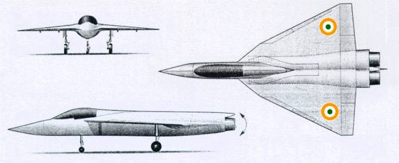
While we spend billions and wait for Rafale, is it worth trying to make a LCA_XL elongated/scaled up version with twin engines to make a medium weight aircraft, while we wait for the AMCA.. I know this topic has been broached before, but dont remember what the BRF community responses were.
Absolutely in the best form Asit, ..and in the highest traditions of Bharat...kudos indeedAsit P wrote:Thanks everyone for your kind words!
Personally I don't like pictures with watermark and hence I deliberately do not watermark any pic clicked by me. Tejas is a national pride and my amateurish pics of Tejas are for one and for all. Even if a single child, teen or a detractor develops a fascination for Tejas through my pics, I would believe that my objective has been met. That said, I also have high regards for those who watermark or copyright their pics (Many of them are journalists or photographers who make a living out of it).
Some random comments: This picture clearly illustrates the two-dimensional nature of a photograph vs. the three-dimensional nature of real objects. Any photograph is actually a two-dimensional projection of a three-dimensional object. If you look at the angle between the length of the craft and the width of the craft, it is indeed 90 degrees. This angle as seen in the picture, is actually not that much different, visually, from angle A (or, DAB, as one would write in 8th grade geometry). In fact, DAB is visually larger angle than the angle we know to be 90 degrees. So, it gets a bit iffy. One reason for this is that the 2 angles are in different planes- one is in the plane of the craft and angle A is more in a 'vertical' plane i.e. parallel to the vertical fin.shiv wrote:Anyone want to try this?
I have given length, wingspan (from Google) and some angles
ABCD is a plane, a parallelogram. The idea is to find the angle at A. Is it possible with the given data?
What is more likely to happen is Rafale gets a large order and MII assembly line adding to several hundred unitsakumarAZ wrote:Off topic:
While we spend billions and wait for Rafale, is it worth trying to make a LCA_XL elongated/scaled up version with twin engines to make a medium weight aircraft, while we wait for the AMCA.. I know this topic has been broached before, but dont remember what the BRF community responses were.
That essentially was the original MCA (out of which came the AMCA) without the two fins. It was expected to have TVC to control all the gyrations.is it worth trying to make a LCA_XL elongated/scaled up version with twin engines

Question is: Is it flying at 22 degrees in that image? How would you find out. It is a math exercise. That's all.indranilroy wrote: The LCA FB admin told you that it is 22 degrees. Go with that.

Indranilroy you have not actually shown why it is not possible to calculate the AoA approximately. All you have done is state opinions. I personally do not find your post convincing and am happy to continue "down the wrong path". Surely you don't believe that learning means always going down one path and not finding out where things can go wrong? In this day and age, with the internet anyone can get any information including stuff like "FB admin says it is 22 deg. Go by that". Sorry. That is not the point. The point is to try and show that the figure obtained from a calculation based on the image can never be right. Can you do that. Yes or no. No need to say anything if you are not interested. I am though and will keep exercising my mind and sharing with others things that fascinate me. Stopping that by saying "wrong path" as if I am trying to mislead and you are not is unnecessary. You could simply keep off the discussion.indranilroy wrote: I am not trying to be a wet blanket. I am stopping people from going down a wrong path. It is the same as saying, unlike what you observe, the sun doesn't orbit the earth.
The only sane proposition that I have read is that can we find the AoA by checking the position of the AoA vane. Nothing else in the last few pages is a mathematical exercise.

Please explain how the direction and angle indicated by a trailing string is different from trailing smoke?indranilroy wrote:You are trying to calculate the incidence of air on the wing based on the airflow behind the wing.
indranilroy wrote: Thank you for the anecdote. This technique is in widespread use in gliders. They are called slip string (when used to check the side slip) and side string (when used to measure the the AoA). These were the very first "aids" the pilots had when sophisticated instruments were not developed yet. If you think about it, the use of "tufts" to visualize airflow around an aeromodel or plane essentially works in the same manner.
The tuft has to be placed at a location where the air incident air is the predominant flow. Otherwise, it will be useless, unless you know how the incident airflow is being modified by the aircraft(again something that Nilesh tried to explain earlier). That is why a test specimen is covered with many tufts. Each tuft depicts the local airflow around the plane, and these directions may be different from one another. By just looking at the direction of the tuft near the wing tip, you can't infer the direction of the tuft at the wingroot, unless you knew a function of correlation. Similarly, you could not infer the direction of the tuft at the leading edge by looking at the tuft at the trailing edge.shiv wrote:Please explain how the direction and angle indicated by a trailing string is different from trailing smoke?indranilroy wrote:You are trying to calculate the incidence of air on the wing based on the airflow behind the wing.indranilroy wrote: Thank you for the anecdote. This technique is in widespread use in gliders. They are called slip string (when used to check the side slip) and side string (when used to measure the the AoA). These were the very first "aids" the pilots had when sophisticated instruments were not developed yet. If you think about it, the use of "tufts" to visualize airflow around an aeromodel or plane essentially works in the same manner.

