PAK-FA and FGFA Thread
Re: PAK-FA and FGFA Thread
^^^^ IIRC, somone posted this link from Shree Sweetman on a really kick-ass solution akin to a "going into a cloaking mode" and a normal mode (for maximum range cruise or performance).
-
Cain Marko
- BRF Oldie
- Posts: 5353
- Joined: 26 Jun 2005 10:26
Re: PAK-FA and FGFA Thread
That would have to be one long assed engine for the compressor blades to show up that close to the intake opening! IOWs, it is rather unlikely to be comp blades. Take a look at the flanker/fulcrum to see how far back the compblades are:

Raosaar is right, the russians would avoid that one mistake if anything. They'd be out of their mind to spend so much effort in edge alignment, crosstooth panels, internal bays, angled stabilizers, and maybe even plasma tech only to have the whole thing shot via such a clear LOS for the comp blades!
They may be lagging behind, but they ain't dumb!
CM.
Re: PAK-FA and FGFA Thread
besides, reduced RCS version is still to take flight..
Re: PAK-FA and FGFA Thread
Sid sir,
You are waking up very late to this particular discussion. It has been around since the first month of PAKFA flight. This pic came out soon after the first few flights. Since then they have been covering the intakes when cameras are around. There was one more picture when Putin went to see the plane. The cover was off and the compressor blades were visible in a picture.
Regarding this particular picture that you have posted it has been established to be a fake. They found out the pic from where the compressor blades was taken too and pasted on this pic.besides if you see the Pakfa pictures very closely where you could peer into the intakes, you would realized that it has chins on either side, which are missing in this "fake" pic.
But it is widely believed that the PAKFA prototype doesn't have its compressor blades completely hidden as yet. There is also talk about a radar blocker. I remember seeing some picture of it. Can't find it now. It looks very different from the one you see on the F-18. It is not in the shape of blades. They look more like S-shaped structures stacked radially around the axis. The plane of each s-shaped "vane" (actually it looked thicker than a vane) is spanwise direction.
Re: PAK-FA and FGFA Thread
Ah found it

Here's a more elegant solution which is being discussed.
http://www.youtube.com/watch?v=SvarEU9oEIY
Between here is what I was saying about how this fake picture was made.

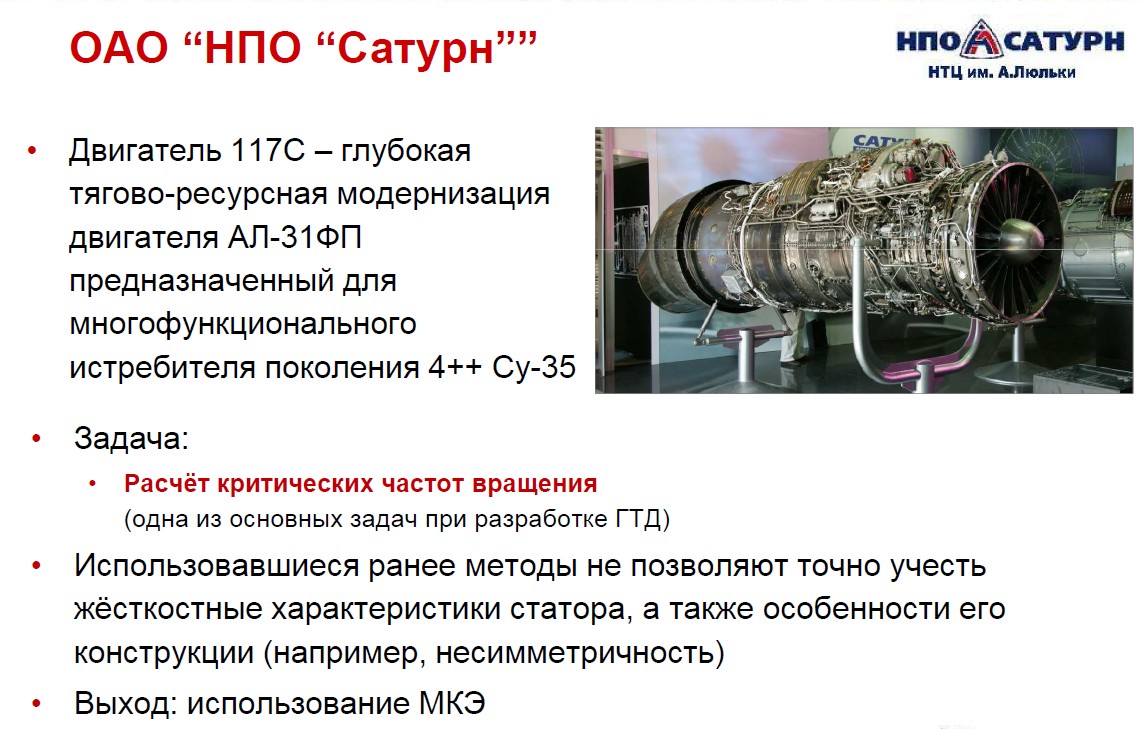
The below picture is from the engine manufacturers display. The fabricator of the fake took the original picture skewed it added graininess and pasted it into the pic. It created a huge flutter when it came out. The debunkers took his fake picture and sharpened it to see this. Even the shadows are the same.
P.S. I hadn't seen HNair sahab's link. I think I had come across that link when I was researching. This was sometime back, so had forgotten
Here's a more elegant solution which is being discussed.
http://www.youtube.com/watch?v=SvarEU9oEIY
Between here is what I was saying about how this fake picture was made.
The below picture is from the engine manufacturers display. The fabricator of the fake took the original picture skewed it added graininess and pasted it into the pic. It created a huge flutter when it came out. The debunkers took his fake picture and sharpened it to see this. Even the shadows are the same.
P.S. I hadn't seen HNair sahab's link. I think I had come across that link when I was researching. This was sometime back, so had forgotten
Re: PAK-FA and FGFA Thread
Thanks Indranil. Next time I will try to shorten my hibernation period 
Re: PAK-FA and FGFA Thread
For the purpose of total time-pass I created this image where I drew an orange line to depict the compressor face and extended lines from each edge of the face though the sides of the intake of an MKI to see exactly where these stealth killing blades of the comp face will be visible under the assumption that no shaping of duct exists and that it is a straight pipe from intake to compressor face. This may be a false assumption.nachiket wrote:Sid, I remember posting that pic here long time back. The consensus then was that we cannot tell from the pic whether what we are seeing are the fan blades or the radar blocker. They do look somewhat similar.
The entire compressor face cannot be seen except in a small cone represented by the blue shaded triangle. It appears that part of the compressor face will be seen in front of and below the MKI. The "cone" where part of the compressor face will be visible will be 35 km wide at a distance of 100 km from a radar situated below and in front of the MKI. An MKI that approaches a target in a zigzag fashion where its nose alternately turns 10 degrees away from the radar will hide the compressor face except for a few moments as it turns. If the plane uses terrain masking it will be invisible in any case until it pops out from behind the terrain. This compressor face tamasha can only be taken so far and no further.

Re: PAK-FA and FGFA Thread
^^
Its not that simple sirji. First of all you are forgetting that MKI flies with a slight aoa even in level flight. But the main point for any a/c is that the radar waves bounce along the whole of inlet. A considerable portion of them reflect off the compressor blades and get out of the inlet. This is why Eurofighter does not employ single s air duct but double s shaped air duct. However, even after employing double s air ducts, the intakes are do not become 100% stealthy.
Think about it. If compressor blades were not such a problem, then why would there be so much takleef? The s and double s intakes cause a lot of turbulence in the air which decrease the performance and thus the resultant thrust of the engine. Equally problematic is the fact that serpentine air ducts take a "lot" of space which is highly undesirable for a stealth aircraft with internal bay. That is why big aircrafts like F-15, Su-27 and Mig-29 never went for serpentine intakes. The small ones like F-16 only went for them not because of any desire for stealth but because they had no choice. Because of their small size, they had to slow the airflow in a very short length. Hence the serpentine air ducts. So, if compressor blade reflectance was not an issue, then both F-22 and PAK-FA would have had straight intakes.
That is why I believe that PAK-FA has got it right. It has considerable curved air duct to hide most of the compressor blades, but not enough curve to cause serious turbulence and wastage of internal space. Rest of the work would be done by radar blocker. However, even that is not without its share of problems. The radar blocker also causes a little turbulence but not nearly enough as compared to serpentine air ducts. Also, it would not bode well if the RAM coating would peel of and get ingested into the engine. However, overall the Russians seem to be going towards a much more efficient solution IMO. The following video showing a possible design of a Russian radar blocker looks highly promising in particular.
http://www.youtube.com/watch?v=SvarEU9oEIY
If they can pull this off, it would totally solve the problem of air turbulence. However, this would need some serious advances in material engineering.
Re: PAK-FA and FGFA Thread
Gaur wrote: Think about it. If compressor blades were not such a problem, then why would there be so much takleef?
I am asking
"How much takleef should be there?"
and
"If radar waves are bouncing off the sides all the way in and all the way out why would a serpentine duct stop that from happening?"
Re: PAK-FA and FGFA Thread
but having a turbulence in the flow direction of the turbine should be fine right? so appropriate internal structuring could control that is a blind thought. Would not that possible to direct the flow with structural guidance?
Re: PAK-FA and FGFA Thread
Who ever takes it the furthest achieves that much more "stealth".This compressor face tamasha can only be taken so far and no further.
However, as one increases the "stealth" capability there is some amount of loss on some other fronts. So, the idea is to find a good marriage between the various factors, which should depend on each air craft and also when each of them were designed.
On the flip side the designers of radars would also be designing and building more and more sensitive detectors. So as the "radar blockers" come into production air crafts, so will these sensitive sensors/detectors.
One thing is clear, if X% stealth is achieved, for an air craft, using a given set of technologies, the same set may or may not produce the same %age on another air craft.
BTW, there was an article that stated that there was concern about a coating on a blade would come off and act as a FO. That is also possible with coating the ducts.
Re: PAK-FA and FGFA Thread
okay, what is wrong with coating it again part of PM?
Re: PAK-FA and FGFA Thread
PAK-FA close up canopy pics link
Re: PAK-FA and FGFA Thread
In fact the same peeling, affecting the skin makes stealth paint maintenance heavy. Add to that the new buzzword - the "wetted area". The skin surface area of a fat bloke is more than that of a thin bloke given that they both have the same basic shape. More internal weapons - more wetted area, smaller payload or range.NRao wrote:BTW, there was an article that stated that there was concern about a coating on a blade would come off and act as a FO. That is also possible with coating the ducts.
Re: PAK-FA and FGFA Thread
Thanks Austin, yeah it is russkie, and so is this video that shows about its materials
http://www.youtube.com/watch?v=8wTa9MTD ... detailpage
http://www.youtube.com/watch?v=8wTa9MTD ... detailpage
Re: PAK-FA and FGFA Thread
Quite a lot actually. Inlet and compressor blades are a major (if not the most important) cause of frontal rcs.shiv wrote:Gaur wrote: Think about it. If compressor blades were not such a problem, then why would there be so much takleef?
I am asking
"How much takleef should be there?"
s-shaped ducts would not stop the radar waves from going out. But they would be scattered and with very less energy to be of much consequence. However, as I have stated earlier, I am personally not a big fan of s shaped intakes specially for a stealth a/cs. That is why I am more impressed by russian approach.and
"If radar waves are bouncing off the sides all the way in and all the way out why would a serpentine duct stop that from happening?"
Turbulance in flow direction is an oxymoron. That would only be laminar flow. Note that whatever bends the radar waves will also bend the air.SaiK wrote:but having a turbulence in the flow direction of the turbine should be fine right?
Yes, the video that I have posted in my earlier post shows such a Russian concept for radar blockers.so appropriate internal structuring could control that is a blind thought. Would not that possible to direct the flow with structural guidance?
It increases the maintainance cost but that sadly comes along with stealth. However, the bigger problem is FOD damage. It will be interesting how the Russians tackle this problem.SaiK wrote:okay, what is wrong with coating it again part of PM?
Re: PAK-FA and FGFA Thread
Gaur, thanks. I am yet to understand why the turbulence (context is directional flow question)should cause a problem in the inlet. What I meant was, since the direction of the air flow would change per the rotation of the turbine blades, then if the design of inlets are such that it causes the air flow (low pressure zone?) similar or in the same direction as it would be in the compression zone, then should it cause a problem? My assumption here is that we could divert the flow by the way inlet design to cause the air flow the way we want by internal structure like as shown in the russkie video that bends the air as it gets sucked in.
I hope I am asking my question clear.
I hope I am asking my question clear.
Re: PAK-FA and FGFA Thread
Why?Gaur wrote: s-shaped ducts would not stop the radar waves from going out. But they would be scattered and with very less energy to be of much consequence. However, as I have stated earlier, I am personally not a big fan of s shaped intakes specially for a stealth a/cs. That is why I am more impressed by russian approach.
-
Arya Sumantra
- BRFite
- Posts: 558
- Joined: 02 Aug 2008 11:47
- Location: Deep Freezer
Re: PAK-FA and FGFA Thread
Sirji, intuitively it seems so but it’s not technically correct. I had seen that argument on a forum and in rebuttal someone posted a nice schematic figure of how Cat's eye works from a google book on stealth. It reminds one of black body Cavity radiation from physics.shiv wrote:The entire compressor face cannot be seen except in a small cone represented by the blue shaded triangle. It appears that part of the compressor face will be seen in front of and below the MKI. The "cone" where part of the compressor face will be visible will be 35 km wide at a distance of 100 km from a radar situated below and in front of the MKI.

There is cavity physics behind it and you can get reflections from engine even at off the line of sight angles although intensity of back reflections should be highest in line of sight cone as you show but not zero at other angles.
Cavity, in a fighter jet, would be the part of fuselage from air-intake and engine ( only referring to front part here, rear’s emissions/reflections is a different discussion)
There are 2 cases in this: (1) from pov of IR emission from engine, the source of radiation (combustion in engine) is inside the cavity in this case- 1-way(exit) of IR emissions and its multiple reflections from cavity (2) from radar reflections pov, the source of radiation (enemy radar) is outside the cavity – 2-way (entry & exit) of radar reflection into and out of cavity
To reduce vulnerability of a fighter one has to minimize both. Just look at the glow on air-intake walls of eff-solah even from side-view at off-angles from line of sight of engine, in an evening/night landing videos.(0.42 to 0.48 secs on http://www.youtube.com/watch?v=kxuOY8XLhp4 ) Gives an idea how much IR signal an enemy could catch even at off angles from compressor face. Same would go for radar waves.
Then there is issue of how cavity walls are designed to minimize multiple reflections. Somewhat similar to basic idea of how auditorium/cinema hall walls are panelled to minimize reverberations and echos. From what the experts talk there seem to be “structures” cladding the inner wall leading from intake upto the engine to minimize the radar reflections. Perhaps this is not too difficult but definitely something that is addressed.
Re: PAK-FA and FGFA Thread
Why the energy would be less? Because the curves would make the radar waves bounce "much" more on the RAM coated air ducts thus decreasing their strength with each bounce. Plus the radar waves coming out would be much more scattered and so the beam width will be less. And as you can very well imagine, strength of the outgoing signal and width of the beam are one of the two most important factors. The other factory is the size of enemy radar's antenna and also the enemy radar's processing power. Unfortunately, we have no control over that. So, we have to make the signal as weak as we can with the beam width as narrow as possible.shiv wrote:Why?Gaur wrote: s-shaped ducts would not stop the radar waves from going out. But they would be scattered and with very less energy to be of much consequence. However, as I have stated earlier, I am personally not a big fan of s shaped intakes specially for a stealth a/cs. That is why I am more impressed by russian approach.
Or are you asking why the Russian approach appeals more to me? That is because their approach result in least air turbulence. But more than that, their approach saves much more internal space which is particularly invaluable in a stealth a/c.
Also, not the radar blocker video that I had posted. It has flexible vanes. I do not know if they will be able to pull that off, but if they do it would be a tremendous achievement. When the stealth is not needed and engine performance is of essence, they can keep the vanes straight and the flow unobstructed.
When stealth is a priority, they can flex the vanes and achieve greater stealth at the cost of lesser engine performance.
Re: PAK-FA and FGFA Thread
I am afraid that I am unable to understand your question. But that may be because of my limited understanding of fluid dynamics. Are you asking why turbulence in air duct will cause any problems? Well, the engine needs as turbulent devoid flow as possible. As turbulence increased, their performance will decrease and after a certain limit they will stall. This is one of the problems faced at high AOA.SaiK wrote:Gaur, thanks. I am yet to understand why the turbulence (context is directional flow question)should cause a problem in the inlet. What I meant was, since the direction of the air flow would change per the rotation of the turbine blades, then if the design of inlets are such that it causes the air flow (low pressure zone?) similar or in the same direction as it would be in the compression zone, then should it cause a problem? My assumption here is that we could divert the flow by the way inlet design to cause the air flow the way we want by internal structure like as shown in the russkie video that bends the air as it gets sucked in.
I hope I am asking my question clear.
Or are you asking why would S-shaped ducts result in turbulence? Well, you can do a home experiment and try to rush water at very high speed through a highly curved pipe. You will see the turbulence at the other end yourself. However, if you are looking for a more mathematical answer, then I am afraid that you would have to ask vina or someone else.
Also you may be under the wrong impression that the Russian solution does not cause turbulence. It does. The difference is that it can adapt according to the need. I have provided my limited understanding on this subject in my previous post to Shiv Sir.
Re: PAK-FA and FGFA Thread
Some interesting pics:


Anyone knows how old the pics are?
Anyone knows how old the pics are?
Re: PAK-FA and FGFA Thread
Gaur wrote:
Or are you asking why the Russian approach appeals more to me? That is because their approach result in least air turbulence. But more than that, their approach saves much more internal space which is particularly invaluable in a stealth a/c.
Also, not the radar blocker video that I had posted. It has flexible vanes. I do not know if they will be able to pull that off, but if they do it would be a tremendous achievement. When the stealth is not needed and engine performance is of essence, they can keep the vanes straight and the flow unobstructed.
When stealth is a priority, they can flex the vanes and achieve greater stealth at the cost of lesser engine performance.
OK. But if exposing a compressor face directly so that it is visible from the intakes does not make all that much of a difference because of reflections along the walls - why is such a song and dance made about visible compressor faces? Or are you saying that hiding them is necessary but not enough and you like the Russian method of hiding them?
Re: PAK-FA and FGFA Thread
I never said that exposing the compressor face directly does not make any difference. It makes all the difference in the world. Hiding them is of paramount importance. What I like about Russian design is the flexibility that it provides. Eg: When PAK-FA is in BVR range, stealth is of greater importance. So, the vanes may be flexed to provide greater stealth at the loss of some engine performance.shiv wrote: OK. But if exposing a compressor face directly so that it is visible from the intakes does not make all that much of a difference because of reflections along the walls - why is such a song and dance made about visible compressor faces? Or are you saying that hiding them is necessary but not enough and you like the Russian method of hiding them?
However, when PAK-FA has to engage in close air combat situations like a dog fight, then radar stealth has little importance and engine performance is more necessary. In that case the vanes will get straightened resulting in optimal engine performance.
This along with much better utilization of internal volume makes me partial towards the Russian design.
PS: Russian posters claim that even with flexed vanes, the turbulence will be much less as compared to s shaped intakes. Don't know if that's true or not though.
Re: PAK-FA and FGFA Thread
In fact this is what triggered this discussion. Would you be able to hazard a guess as to how much difference (say in terms of percentage) it would make to hide the compressor face without doing anything else to the ducts. There is a specific reason I ask this question. I created a diagram (possibly very inaccurate) that estimated the cone in front of an MKI in which at least part of the compressor face would be visible. That cone is mostly below the level of the aircraft and according to my estimate is 35 km wide at a distance of 100 km from the MKI. The intakes are basically invisible from above. And the compressor face would be invisible at an angle of more than 15 degrees on either side. Would that not cause a drastic drop in radar returns off to one side despite reflections within the duct?Gaur wrote: I never said that exposing the compressor face directly does not make any difference. It makes all the difference in the world. Hiding them is of paramount importance.
How strong would the radar returns be outside this cone of direct compressor face visibility in terms of percentage? (any estimate will do if you happen to have an idea) Also the entire compressor face is almost impossible to see via the intakes, and the further to the sides one goes - the less one sees of the compressor face. Would one not get an attenuation of the signal with the most powerful signal being directly in front where the biggest proportion of compressor face is seen?
The implication of this is, as far as I can tell, that the MKI would be distinctly unstealthy in a 35 mile wide cone directly ahead and below (at a range of 100 km from the radar) Fewer radar signals related to the compressor face would be visible off to one side, despite reflections along the the walls.
Re: PAK-FA and FGFA Thread
Isn't that the flatter nozzles are larger in size...quite unsymmetrical also...!Gaur wrote:Some interesting pics:
Anyone knows how old the pics are?
Re: PAK-FA and FGFA Thread
Here is a link...It saysGaur wrote:Anyone knows how old the pics are?
The flying lab derived from the T10-26 was used to test the asymmetric swivelling nozzle. In 1990, the T10U-5 combat trainer was converted into a flying lab whose left engine was fitted with a flat variable-geometry nozzle.
Re: PAK-FA and FGFA Thread
^^
Sumshyam,
Thanks for the links. I knew that Russians had once experimented with flat nozzles much before the development of MKI. It is nice to know more about it.
Sumshyam,
Thanks for the links. I knew that Russians had once experimented with flat nozzles much before the development of MKI. It is nice to know more about it.
Re: PAK-FA and FGFA Thread
Shiv Sir,
Unfortunately, I am in no position to hazard any guess regarding the percentages you ask. All the little that I know has been gleaned from open sources on internet and no where I have come across any percentage.
However, the importance of hiding compressor face has been emphasized on at every place. Other important factors that I have come across are intake's shape and orientation, randome, cockpit, ventral fins and external stores.
As for your MKI calculations, I think Arya Sumantra's explanation is highly explanatory. The only thing that I can add is that you seem to have ignored the slight AOA at which MKI flies because of which the drop in the nose fails to cover the intake like it does on the ground. This would matter to calculate theoretical frontal rcs which takes into account only head on engagement at same altitude.
This is what I am talking about:

You may argue that this does not matter because the enemy fighter will not necessary engage with perfect head on engagement. I agree. That is why hiding only the compressor blades will not make the a/c stealthy. Anyways, I am not trying to debate regarding the rcs of MKI in various situations. I am only discussing the importance of compressor blades in general terms and not for any specific fighter.
What I am trying to say is that compressor is only a part of the equation albeit an important one. This one of the reasons why some people (which I guess includes you) are not big fans of stealth. It takes too much effort to achieve stealth but only little problem/deficiency to destroy it.
Unfortunately, I am in no position to hazard any guess regarding the percentages you ask. All the little that I know has been gleaned from open sources on internet and no where I have come across any percentage.
However, the importance of hiding compressor face has been emphasized on at every place. Other important factors that I have come across are intake's shape and orientation, randome, cockpit, ventral fins and external stores.
As for your MKI calculations, I think Arya Sumantra's explanation is highly explanatory. The only thing that I can add is that you seem to have ignored the slight AOA at which MKI flies because of which the drop in the nose fails to cover the intake like it does on the ground. This would matter to calculate theoretical frontal rcs which takes into account only head on engagement at same altitude.
This is what I am talking about:
You may argue that this does not matter because the enemy fighter will not necessary engage with perfect head on engagement. I agree. That is why hiding only the compressor blades will not make the a/c stealthy. Anyways, I am not trying to debate regarding the rcs of MKI in various situations. I am only discussing the importance of compressor blades in general terms and not for any specific fighter.
What I am trying to say is that compressor is only a part of the equation albeit an important one. This one of the reasons why some people (which I guess includes you) are not big fans of stealth. It takes too much effort to achieve stealth but only little problem/deficiency to destroy it.
Re: PAK-FA and FGFA Thread
One wonders how much of a rcs compromise would result from a twin seat canopy?. From the various media reports it would appear that the single seater is now totally off the radar for the IAF(there was a suggestion earlier that around 50 would be bought) .
Re: PAK-FA and FGFA Thread
Even the raptor is not "totally" off the radar. It is all left canopy shapes and internal design that is exposed to the em waves. There are canopy coatings with certain Fe material composites to deflect off the waves with certain shape features. It all depends on which approach they would want to take.
-
Arya Sumantra
- BRFite
- Posts: 558
- Joined: 02 Aug 2008 11:47
- Location: Deep Freezer
Re: PAK-FA and FGFA Thread
Because you want to avoid any direct reflections(highest intensity signals) from compressor face. Compressor face is a conducting cavity wall after all.shiv wrote: OK. But if exposing a compressor face directly so that it is visible from the intakes does not make all that much of a difference because of reflections along the walls - why is such a song and dance made about visible compressor faces?

In case of an intake without concealed compressor faces, the radar backreflection is made of 2 components: (1) Direct reflections(strong) from compressor faces (2) Indirect reflections(weak) reaching after multiple bounces from intake walls.
The yellow cone(in figure) as you had shown, actually contains (1) PLUS (2) whereas Orange zone is not zero but (2) ONLY.
The enemy E as shown in schematic below subtends an angle(theta) that puts him in orange zone whereby he is still able to see the multiple bounced reflections from engine face. Detection then depends on enemy’s receiver’s sensitivity also if signal strength gets below sensitivity threshold.
For sake of discussion, a highly generalized profile of received Intensity versus Angle of observer/enemy is shown in figure below. The intensity of engine backreflections is highest in the line of sight and tapers off as your angle increases upto intake edge whereafter signal becomes zero. The question mark exists because these plots are speculated from logic rather than a precise mathematical formula of Intensity as a function of theta which would be somewhat rigorous but definitely more reliable.
In case of a convoluted intake with concealed compressor face, what enemy sees is entirely made up of Indirect reflections attenuated after multiple bounces on intake walls. Besides, the number of bounces should be higher in case of an s-duct compared to straight duct. Hence the generally depressed Intensity profile of back reflection as compared to that for a straight duct.
JMT
Re: PAK-FA and FGFA Thread
Again, we could have straight ducts, and like Rafale have the fuselage curved in more to prevent direct frontal RCS. That would be a odd shaped one., but definitely one would get more side lobe space for side aesa radar housing. Since, pak-fa has taken the duct all under the wings, the only option sounds like the radar blocker technology that has many deflectors/absorbers within the duct itself.
They could also push the engine a little bit projecting up decreasing the frontal RCS, by the same distance which is visible in the pic above. So, that they don't have to quite a bit of sharp curved S shapes.
BTW, it would be interesting if any next gen composites that might help in absorptions against deflections, and are part of the airframe rather a coating technology.
Re: PAK-FA and FGFA Thread
They have pushed the engine up. The duct is not straight as Su-30, Mig-29, F-15 etc. It very much has a curve but it is not exactly s-shaped.SaiK wrote: They could also push the engine a little bit projecting up decreasing the frontal RCS, by the same distance which is visible in the pic above. So, that they don't have to quite a bit of sharp curved S shapes.
Re: PAK-FA and FGFA Thread
Even if the engine is directly in line with the intake - all that is needed is some internal shaping of the duct to prevent the compressor face from being directly visible for most part.
Arya Sumatra - thanks for that informative diagram. I will be back with a query on that soon.
Arya Sumatra - thanks for that informative diagram. I will be back with a query on that soon.
Re: PAK-FA and FGFA Thread
if that 2nd diagram be true, nothing of the engine face would be visible looking from front due to the lateral curve.
Re: PAK-FA and FGFA Thread
The second dig is on the anterior-posterios axis where as the first diagram on dorsal-ventral axis. Who made those dig up? Let us wait for the second prototype to take to skies and may get to see if they have looked at this RCS aspect.
Re: PAK-FA and FGFA Thread
If the Russian posters are anything to go by (usually they are), the second flying prototype will be near identical to T-50-1 with the main difference being the addition of more avionics. At present the static testbed T-50-2 is serving as the avionics prototype with the T-50-1 flying with only the critical avionic systems.SaiK wrote:The second dig is on the anterior-posterios axis where as the first diagram on dorsal-ventral axis. Who made those dig up? Let us wait for the second prototype to take to skies and may get to see if they have looked at this RCS aspect.
The third flying prototype is expected to incorporate some major changes while the fourth flying prototype will be the be of production standard.