Any communication over a longer distance involves modulation. So just before entering into the satellite specific subjects we will do a run through on Modulations. ( Now in a more formal way ).
BASIC COMPONENTS OF COMMUNICATION:
As explained in earlier post three components are always involved in a communication:
i. An Information or Data Or Message which is to be sent. In technical parlance it is called as Baseband ( BB ).
ii. A Carrier which is modulated by changing one of its component ( Amplitude or Frequency or Phase ) based on the value of Baseband
iii. And A Medium through which the modulated carrier will travel. It could be a Copper wire or space or Fibre cable through which a light is passed.
iv. We also saw that the Baseband can be Anlog or Digital and also seen that Digital is nothing but converting the analog
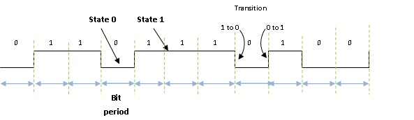
baseband into a digital value by ( this is a new word but again old wine in new bottle ) Quantization. ( remember 1000 Rs converted to 010101011000 format we said there will be Rounding Off error … well that is the process of Quantization and that error is the Quantization error. An important property of BB in digital case is that it will be generated at a fixed frequency called Data Rate. The change of state from 1 to 0 or 0 to 1 is called as a Transition.
Some terms associated with digital signals are graphically shown here and are self explanatory:
From now onwards we will concentrate only on Digital signals because Analog modulation is rarely in use now a days. Even in Digital modulation our main focus will be on Phase Modulation … again because that is the one which is in use for most of the high efficiency systems. What is high efficiency? We will shortly see that because before that we must understand what is Bandwidth and we will try to understand that right away.
SPECTRUM AND BANDWIDTH:
Recall what is a carrier. It is a sine wave of a certain frequency. Suppose that this frequency is 70 MHz and has an amplitude of 1V. How will it appear on a graph having Frequency as X axis and amplitude as Y axis.? It will look like shown in drawing below. Idealy it should look a thin fine single line.
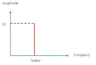
This representation of Amplitude versus Frequency is called as Frequency Spectrum. A practical Frequency spectrum as seen on an instrument called Spectrum Analyzer is shown in photograph.
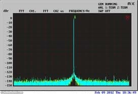
Although apparently it looks like a clean vertical line if we expand it to a large extent then we see very small jitter in frequency.
It is not a single line because practically there is never a rock stable frequency. It will always jump in phase and frequency ( A 70 MHz oscillator will give 70.00001 MHz,70.000024 MHz, 69.00002MHz, 70.0000 MHz, 69.000042 MHz and so on at different instances . Naturally most of these wanderings will be near the exact frequency but some stray frequencies will also show their presence on spectrum display ) causing the thickness instead of a clean line.
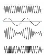
That was about a clean sinewave. How does the spectrum of a square wave look like? To answer that let’s see how a square wave can be generated using sine waves. ( Please ignore the imperfections due to hand-drawn figure )
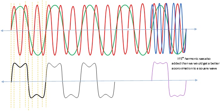
In this diagram two sine waves ( Red and Green shown on top portion )with frequencies of f and 3f are added. ( i.e. if f= 1khz then 3f=3khz or if f=1 MHz then 3f= 3MHz … what is important is that they are in the ratio of 1:3 or second frequency should be 3 times the first one. Such frequencies are called as harmonics .. Red is the 3rd harmonic of Green ) The addition results in a near square wave as shown in bottom portion.
If we add next odd harmonic ( i.e. 5f ) then a we get a waveform which is still nearer to a square wave as shown in right bottom portion of figure.
Addition of more odd harmonics 7f,9f … will bring the output waveform still nearer to a perfect square wave.
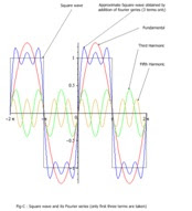
A professionally drawn image with higher harmonics is reproduced here on left from a very good article (
http://www.skm-eleksys.com/2010/10/four ... rical.html ).
In converse we can say that a square wave is made up of many odd harmonics of sine wave, the lowest frequency ( f ) being equal to the square wave frequency.So its spectrum should show all the odd harmonics that it is made up of.
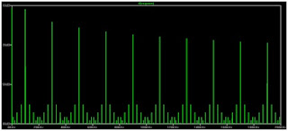
Actual spectrum of a square wave is on right. Notice several vertical thin lines each representing a sine wave. ( The small components near bottom are due to imperfection in squarewave used for making the spectrum display and we can ignore them. )
Just for academic interest. In the above description we have taken odd harmonics. What happens we take even harmonics and add them? We get a Triangular wave instead of a square wave.
Such studies is the subject of Fourier Analysis and Harmonic Analysis. We will not go in those details here.
Decibel, db, dbm, dbW .. etc Explained
Although in previous figure amplitude was shown as 1 Volt for clarity, any Spectrum Analyzer almost always represents the Y Axis in dbm that is ‘ the amount of RF power delivered to load when referred to 1 mw’. Please do not faint I will explain.
In electrical systems voltage is a measure of amplitude. ( Like we say 230V is the voltage of household supply in India ). When this voltage is connected to a 100W bulb, then 230V is applied across the filament of lamp and it causes current to flow through filament which heats the filament and it starts glowing due to the heat produced. Naturally the filament is causing a load of( V^2/R ) which is 100W. ( R is the resistance of filament of bulb ).
Same thing happens In Radio Frequency Communications also. The RF signal from transmitter ( Technically called SOURCE ) is connected to a LOAD ( Equivalent of Lamp in electrical circuit ). The RF energy generated in Source is transferred to the load.
Now here comes the difference. In electrical circuit we don’t bother much about the capacity of Source and the Load because the source has almost infinite capacity ( compared to a single lamp that we have connected ). But in RF connections it is not so simple. Rf energy is generated with a highly complex oscillator and has to always be transferred in total to the load ( We will see later if the two are mismatched then there is possibility of them getting burnt or an arcing to happen ) , and this happens when the source and the load are perfectly matched.
The source generates 1 W power. The source has an internal impedance ( impedance is similar to resistance but its value changes with frequency ) of 50 Ohms. This power is connected to the load which is also 50 Ohms. One more concept that now needs to be explained is that the line connecting two devices in RF circuit is called a transmission line and it also has an impedance. The connection between source and Load is done through a line which also has an impedance of 50 ohms.
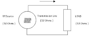
That is Maximum power gets transferred from source to load when the two are matched.
Now we said 1 Watt of power. In RF circuits Watt or similar units are rarely used.
We use what is called as a decibel system. It is a logarithmic system to show a ratio between two powers i.e. 10*log(ratio).
By definition decibel is represented by 20*log(voltage ratio) or 10*log( power ratio )
E.g. Suppose there is an amplifier which amplifies the signal
voltage 25 times. So we represent voltage gain in db as
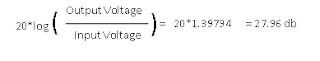
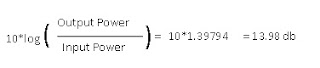
Instead suppose the Power ratio was 25, then we get
That explains about how relative ratios are shown in db. But we also must be able to define some absolute levels. ( Ratio of 25 can mean 1W is amplified to 25W, or 100W is amplified to 2500W. it is only a ratio.
We said earlier .. The carrier amplitude is 1V. Now this is an absolute value. You can’t have .2V as 1V or 20V as 1V. It is an absolute value 1Volt. )
In such cases we have to define ratio with some fixed ( absolute ) level.
E.g. 5V is 5 times of 1V so it will be computed as 20log( 5/1 ) and since it is defined w.r.t 1V reference level it is called as dbV. So 5V is = 13.98 dbV.
Some other Reference Decibels that we regularly come across are,
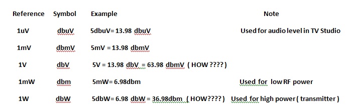
A Common approximation used for quick calculation is Power ratio of 2 ( doubleor half the power ) = 3 db ( actually it is 3.010) . Some more quickies are 10 times power = 10 db, 2 times voltage = 6 db, 10 times voltage = 20db.
PSK, BPSK, QPSK Modulation systems
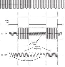
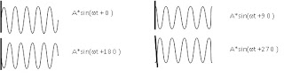
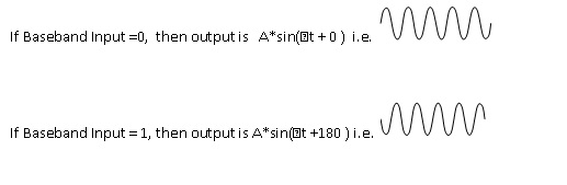
In an earlier post we have seen that the carrier has a form A*sin(ωt+ɸ), ɸ, the phase, specifies where in its cycle the oscillation begins at t = 0. Adjacent figure shows 4 possibilities of how 90 deg phase shifted waveforms will look like. Thick line on left is the start time indicator, ( T=0 ); and one can see how the four waveforms start at different phases at T=0.
Such type of modulation where the Phase of the carrier is changed as per the Digital value of Baseband is called as Phase Shift Keying (PSK). This gives various possibilities and therefore is most preferred where high data rates are involved. Two most common PSK modulation schemes are BI Phase Shift Keying ( BPSK ) and Quadrature Phase Shift Keying ( QPSK ). We will go in some detail about these two.
How can we generate this BPSK modulation? Right side figure symbolically shows a BPSK modulator.
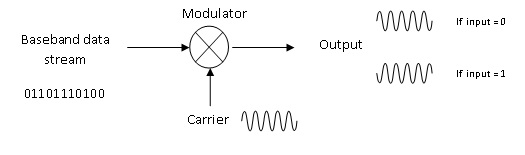
The phase of the carrier is changed as per the input value of Baseband resulting in two types of outputs:
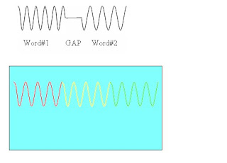
A combo graph of Baseband and Modulated carrier is shown below for the baseband data stream '01101110100'
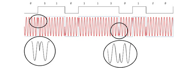
Notice that whenever BB changes its state from 0 to 1 or 1 to 0 , the carrier changes phase by 180 o ( see expanded view ).
Instead of just 180 we can have 4 waveforms spaced at 0, 90, 180 and 270. But there is a small problem. In BPSK we had 0 or 1 as the two states of Baseband but for QPSK we require 4 states. How we do that? To overcome this we now use four states, each consisting of a pair of bits from two data streams viz 00, 01, 10 and 11. Each pair is called as a symbol and so for each symbol there will be a distinct state on output carrier as plotted in next diagram.
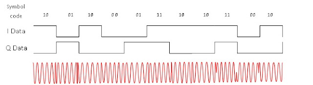
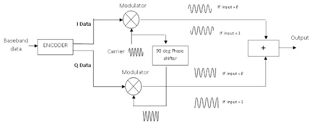
For generationg these symbol codes an encoder is used which strips the incoming serial data into two streams I and Q ( They are actually abbreviations for In-Phase and Quadrature ) which are applied to each half of modulator.At the receiving end a special decoder is used which will combine the demodulated I and Q data streams into a single serial data output which is the replica of original data. Encoder actually serves another very important function, that of security key. The encoding is done by using some algorithm and one can keep his data secure by keeping the encoding algorithm a secret. A corresponding Decoding Key is required at receiving end and data reproduction can be done only by using that key.
We can imagine a QPSK modulator to have been made up of two identical BPSK modulators fed with quadrature phased carriers for modulation. This results in one giving a 0/180 phase outputs and the other givinging 90/270 phase outputs which connected to an adder which combines both the BPSKs.
In our next dose we will cover demodulators and some other communications topics.