ISRO did test Vikram. There is information available about it. To compensate for the moon’s less gravity, it appears they used helium balloons. Which is proabably sufficient 99 out of 100 times given thrusters are operating nominally. If for that rare instance the thrusters don’t operate as intended, it *may* be failure.
Simulating a lander in 1/6 gravity with no atmosphere is very difficult.
Chandrayan-2 Mission
-
Mort Walker
- BRF Oldie
- Posts: 10039
- Joined: 31 May 2004 11:31
- Location: The rings around Uranus.
Re: Chandrayan-2 Mission
A critical reason to establish communication is to download the data on board Vikram to clearly figure out the cause of the problem. Vikram needs a lot more testing and this data is invaluable. Tough luck on losing it completely.
Re: Chandrayan-2 Mission
My point was related to having two-point thrust balancing the craft once it changed its attitude from horizontal to vertical (for landing). Its difficult to balance on two points, 3-point system would be a more stable and 4-point system would give additional redundancy.chetak wrote:JayS wrote:
A liquid fuel thruster should not have very complex valve opening to thrust function, for hypergolic fuels, I'd imagine. And by now ISRO must be having tons of data to correlate performance of nozzles in tests in their test cells vs performance in vacuum. (would gravity matter for thrust??How?? ) Are they using a new rocket motors with new fuel and/or architecture..?? I'd expect them using proven rocket motors for this application.
It makes sense that there was higher gain than expected which could have pushed the control system in self induced oscillations. And perhaps there was not enough time available to recover there after.
I read somewhere that only two thrusters were used for fine braking out of four. Is that correct info..?? I don't know what was the geometric config of the thrusters, but it sound odd to use two thrusters. If this is correct, I am perplexed why ISRO used this kind of setup. I frankly don't think this is correct.
If the landing site was not what the mission specialists expected it to be, they catered for the alternate site some distance away so they would have catered for extra fuel.
in the risk analysis, no one would agree to go that far in a seriously complex mission and then run out of fuel by skimping on the amount carried onboard. In fact, they would have added a risk correlated safety margin to the fuel load.
so the two thruster theory may be a longish shot and also, it's much more risk prone than the four thruster approach that they were already using.
loss of signal is a flight critical parameter and it would have been factored in at all stages of the approach and the best solution, under such a situation would have been to switch to a completely autonomous mode and perform a pre programmed and failsafe landing.
Maybe the switch did not take place or take place in time to make the difference. The fact that there were oscillations is borne out by the doppler and it's likely that some parameter may have exceeded the design limits, setting up a hitherto uninvestigated failure chain.
Vikram does have additional motors for attitude control but they are much smaller in comparison.
Re: Chandrayan-2 Mission
JayS sirji,JayS wrote:My point was related to having two-point thrust balancing the craft once it changed its attitude from horizontal to vertical (for landing). Its difficult to balance on two points, 3-point system would be a more stable and 4-point system would give additional redundancy.chetak wrote:
If the landing site was not what the mission specialists expected it to be, they catered for the alternate site some distance away so they would have catered for extra fuel.
in the risk analysis, no one would agree to go that far in a seriously complex mission and then run out of fuel by skimping on the amount carried onboard. In fact, they would have added a risk correlated safety margin to the fuel load.
so the two thruster theory may be a longish shot and also, it's much more risk prone than the four thruster approach that they were already using.
loss of signal is a flight critical parameter and it would have been factored in at all stages of the approach and the best solution, under such a situation would have been to switch to a completely autonomous mode and perform a pre programmed and failsafe landing.
Maybe the switch did not take place or take place in time to make the difference. The fact that there were oscillations is borne out by the doppler and it's likely that some parameter may have exceeded the design limits, setting up a hitherto uninvestigated failure chain.
Vikram does have additional motors for attitude control but they are much smaller in comparison.
I got your point in the earlier post.
with a two point thrust, even the slightest mismatch could induce a coupling moment to set in quickly.
Wouldn't that be the riskier way to go, assuming that fuel may not have been a constraint.
No one has yet explained or even speculated about the oscillations that were reflected in the doppler.
there may be some corrective mechanism in play here to restore the attitude to the expected value.
Re: Chandrayan-2 Mission
If the other 2 thrusters(which were shut down) are fired will not that oppose the turning movement. The craft gimbaled along the axis perpendicular to the sides on which thrusters were shut down.
Re: Chandrayan-2 Mission
The lag in the signal reaching the lander would have caused some difficulties and its presuming that the lander antenna was correctly/optimally orientedarvin wrote:If the other 2 thrusters(which were shut down) are fired will not that oppose the turning movement. The craft gimbaled along the axis perpendicular to the sides on which thrusters were shut down.
Re: Chandrayan-2 Mission
my query was regarding fine breaking sequence with 2 thrusters and not after it landed.
https://directory.eoportal.org/web/eopo ... 4rS13eHerb
The link has a figure saying only 2 were used in fine breaking.
https://directory.eoportal.org/web/eopo ... 4rS13eHerb
The link has a figure saying only 2 were used in fine breaking.
Re: Chandrayan-2 Mission
JayS, What if the 500m shortfall from target landing zone had rocks and caused the lander to tilt sideways.
And communications were lost at time of velocity=58m/sec.
Maybe the lander went autopilot and did land safely but tilted sideways.
Now the need is to get the signal through the blocked antenna?
ISRO labs would have a mock-up on ground and tilt it to see what dB is needed to send a signal to the antenna?
Re: Chandrayan-2 Mission
Thanks arvin for the link!!!

What if it tilted on the side of the ramp?
From the hopeful comments from ISRO its tilted the other side.
Also does the lander have sideways thrusters that can be fired to upright it?
Even if they are small thurst engines..
Some thing like 'dum laga ke aisa'!
What if it tilted on the side of the ramp?
From the hopeful comments from ISRO its tilted the other side.
Also does the lander have sideways thrusters that can be fired to upright it?
Even if they are small thurst engines..
Some thing like 'dum laga ke aisa'!
Re: Chandrayan-2 Mission
Lander must have sideways vernier thrusters to change the attitude from horizontal to vertical while it was in the landing mode.
Are those small black nozzles near the legs the vernier thrusters?
Are those small black nozzles near the legs the vernier thrusters?
-
Nalla Baalu
- BRFite
- Posts: 153
- Joined: 24 Aug 2006 07:16
- Location: Yerramandi, Dhoolpeta
Re: Chandrayan-2 Mission
R saar, entire descent was autonomous without any control signal from the Orbiter or the MCC.
ramana wrote:JayS, What if the 500m shortfall from target landing zone had rocks and caused the lander to tilt sideways.
And communications were lost at time of velocity=58m/sec.
Maybe the lander went autopilot and did land safely but tilted sideways.
Now the need is to get the signal through the blocked antenna?
ISRO labs would have a mock-up on ground and tilt it to see what dB is needed to send a signal to the antenna?
Re: Chandrayan-2 Mission
So it means lander did its thing except comms were lost for some reason.
And the picture shows its tilted on its side.
Usually there are twin telemetry transmitters for data redundancy. May not be full power.
OK lets hope and wait.
And the picture shows its tilted on its side.
Usually there are twin telemetry transmitters for data redundancy. May not be full power.
OK lets hope and wait.
-
UlanBatori
- BRF Oldie
- Posts: 14045
- Joined: 11 Aug 2016 06:14
Re: Chandrayan-2 Mission
Sorry but couldn't help noticing that the V-Kram is shaped very much like the B-M, pre-1992.  Any wonder that it landed on its head, hain?
What antenna is dome-shaped convex I wonder.
What antenna is dome-shaped convex I wonder.
Re: Chandrayan-2 Mission
Can some one read and expaling ref 9 of Arvin's link posted here
It has lander propulsion system description.9) Abhishek Sharma, Deepak Kumar Agarwal, Jagadeesa Chandra Pisharady, S. Sunil Kumar, "Plume Flow Field Analysis for Lander Propulsion System of Chandrayaan-2 Mission," 68th International Astronautical Congress (IAC), Adelaide, Australia, September 2017, URL: https://iafastro.directory/iac/proceedings/IAC-17/
IAC-17/C4/3/manuscripts/IAC-17,C4,3,3,x38219.pdf
Re: Chandrayan-2 Mission
UB that link posted by arvin has many ref papers and articles.
Eg read this paper at AIAA:
Eg read this paper at AIAA:
1) Venkatesan Sundararajan, "Overview and Technical Architecture of India's Chandrayaan-2 Mission to the Moon," AIAA SciTech Forum, 8–12 January 2018, Kissimmee, Florida, 2018 AIAA Aerospace Sciences Meeting,
URL: http://epizodsspace.airbase.ru/bibl/ino ... yaan-2.pdf
Re: Chandrayan-2 Mission
Isn't the dome antenna omni directional. Each is a segment of sphere.
-
Varoon Shekhar
- BRF Oldie
- Posts: 2178
- Joined: 03 Jan 2010 23:26
Re: Chandrayan-2 Mission
No fan of NDTV, but they have had two shows about the Vikram Lander after Sept 7th, and both were balanced and essentially positive. No jibes at ISRO or PM Modi. One was hosted by Vishnu Som.
Re: Chandrayan-2 Mission
someone from ISRO/Govt must have busted their b@!!$Varoon Shekhar wrote:No fan of NDTV, but they have had two shows about the Vikram Lander after Sept 7th, and both were balanced and essentially positive. No jibes at ISRO or PM Modi. One was hosted by Vishnu Som.
Re: Chandrayan-2 Mission
Personal opinions deleted. Doesn't add anything meaningful.
-
UlanBatori
- BRF Oldie
- Posts: 14045
- Joined: 11 Aug 2016 06:14
Re: Chandrayan-2 Mission
From kagaz-ul-aiaa:
The sensors are configured for inertial navigation from separation to the end of rough braking and the absolute sensors determine the position and velocity with respect to the landing site to guide the lander beyond the rough braking phase to the identified site. The lander Navigation guidance and control will be autonomous from separation onwards and must ensure a precise, safe and soft landing on the lunar surface. {so comm failure with Bengaluru is not excuse to go on strike} The braking thrust for decelerating the lander is provided by four nos. of liquid engines. The attitude of the lander is maintained with eight nos. of thrusters. The lander leg mechanism ensures that the energy at touch down is absorbed and all the lander systems are integral and stable for further conduct of payload deployments and science on moon. Each leg consists of a telescopic leg assembly with crushable damper material in the leg and foot pad. Extensive analysis and tests are done for thelander leg mechanism to ensure stability under extreme terrain conditionsand terminal velocity. {values not given but they know} The TTC communication between the Lander –IDSN is in S band and the payload data is transmitted by a high torque dual gimbal antenna. The Lander has a TM-TC data handling system with inbuilt storage. The Chandrayaan-2 Bullock-less Bailgadi (BLBG) is stowed in the lander during launch and upon landing the ramps are deployed and BLBG starts its journey on the lunar surface. The Lander payloads will be deployed on landing.
...
At the end of the rough braking phase [~7 km], the Hazard avoidance sensors will sense the position and velocity of the Lander with reference to the landing site. Based on the relative position and velocity with respect to the pre-determined landing site on the moon surface, the further trajectory is planned on board and the sensors along with actuators will guide the Lander to a position over the landing site [~100 m]. At this point, the Lander hovers over the site and the hazard avoidance sensor will determine the safest landing point in the near vicinity and the Lander will be maneuvered to this point. At a height of 2m, upon ensuring that the relative velocity with reference to moon surface is zero, the braking engines are cut off. The Lander freely falls to the surface and the landing leg mechanism will absorb the impact loads and ensure the integrity of the Lander for further operations. The entire operation from separation to touch downis fully autonomous and must be performed by the onboard computers in the Lander without any intervention from ground.
-
UlanBatori
- BRF Oldie
- Posts: 14045
- Joined: 11 Aug 2016 06:14
Re: Chandrayan-2 Mission
Based on the above, UBCN stands by our analysis given on prior page. Multiple failures occurred but free-fall was not from any great height. Somehow Terrain Approval Aphsar (TA3) software was not able to function. So first failure was whatever caused the comm failure to Orbiter. But even then, if stable, the autonomous landing system should have taken it to soft landing at a decent place. So there was another failure. The hover at 100m probably did not occur - or did it? Maybe the Chehra -ul-Id (CID) system did not work, it did not recognize the place?
But let's wait for the sun to come up sufficiently: I think V-Kram is going to call home and complain.
But let's wait for the sun to come up sufficiently: I think V-Kram is going to call home and complain.
Last edited by UlanBatori on 09 Sep 2019 23:39, edited 1 time in total.
Re: Chandrayan-2 Mission
Its asking for login. Got the same paper here.ramana wrote:Can some one read and expaling ref 9 of Arvin's link posted hereIt has lander propulsion system description.9) Abhishek Sharma, Deepak Kumar Agarwal, Jagadeesa Chandra Pisharady, S. Sunil Kumar, "Plume Flow Field Analysis for Lander Propulsion System of Chandrayaan-2 Mission," 68th International Astronautical Congress (IAC), Adelaide, Australia, September 2017, URL: https://iafastro.directory/iac/proceedings/IAC-17/
IAC-17/C4/3/manuscripts/IAC-17,C4,3,3,x38219.pdf
https://www.researchgate.net/publicatio ... -2_MISSION
CFD study is carried out for clustered 4 nozzle configuration of 800N thrusters under simultaneous firing during braking phase of Chandrayaan-2 mission. Plume-plume interaction is observed to initiate at an axial location of 0.2 m from the thruster nozzle exit. The interaction of plumes results in high static pressure and temperature zones. Entrainment zone is observed to form between 4 engines, which is due to high static pressure at the interaction plane and resultant updraft plume. Surface incident radiative and convective heat flux on the base plate and lander leg structure is estimated for appropriate design of thermal protection of lander. The magnitude of convective heat load on lander structures was seen to be lower than radiative heat flux due to low plume density. Incident and convective heat flux plots indicated that, nozzle throat will act as the main source of radiative and convective heating of lander components, with minor contribution from updraft plume.
Re: Chandrayan-2 Mission
UBCN,
Give them a day. 10th things should return to normal. Comms and all.
Give them a day. 10th things should return to normal. Comms and all.
Re: Chandrayan-2 Mission
As I said before - and quite a few times before - , is is well known, Vikram is autonomous. This means, it is designed to land on moon with NO outside input - even if connection to outside world is completely lost. (I AM ignoring many absolutely silly and unscientific speculation spewed out even in Brf dhaga).
One does NOT need command from earth or CY2 for Vikram to do successful landing. So it won't be surprising if landing is better than worse-case hard landing. NO, it does not mean everything went perfect, but it does not mean that Vikram was completely lost.
What we do know -
- Vikram landed pretty close to where it was supposed to land.
- It is in one piece. (more or less)
- The landing, by no means perfect, was not a horrible crash either.
- The solar panels, (for power), and omni-direction antennas are designed to work - they may work we may have to work.
- (OTOH - a broken cable from transmitter to antennae or something blocking the line of site or something quite simple may be enough to cause no communication)
- ISRO people are neither deshdrohi's nor idiots
-
UlanBatori
- BRF Oldie
- Posts: 14045
- Joined: 11 Aug 2016 06:14
Re: Chandrayan-2 Mission
Paper says that CY-1 (not CY-2) was forced to raise orbit from 100km to 200km to reduce heating. Is this radiant heat from lunar day? Wow! I thought it only reached 200C which should cause radiant heating only like an average day in Sriharikota summer, hain? Doesn't the orbiter rotate to distribute heating from one side to the other?
Last edited by UlanBatori on 09 Sep 2019 23:44, edited 1 time in total.
-
Mort Walker
- BRF Oldie
- Posts: 10039
- Joined: 31 May 2004 11:31
- Location: The rings around Uranus.
Re: Chandrayan-2 Mission
I hope you are right. Does anyone know what the angle of the sun is on the south pole of the moon during September?NRao wrote:UBCN,
Give them a day. 10th things should return to normal. Comms and all.
-
UlanBatori
- BRF Oldie
- Posts: 14045
- Joined: 11 Aug 2016 06:14
Re: Chandrayan-2 Mission
Full Moon is Sep. 14, so right now should be half-way there per madarssa math. Which is why the timing was what it was. Maybe just coming over the horizon at the South pole - but V-Kram may be in shadow if it landed wrong side of a slope, which should also get fixed soon. The panels were designed (truncated pyramid) to be normal to a very shallow sun, but with the craft on its side, the visible panel is at a much shallower angle, so very little power generation. Need middday I think, before V-Kram decides to wake up.
Has there been an actual photo published of the lander in its present state? At least a sketch?
Has there been an actual photo published of the lander in its present state? At least a sketch?
Re: Chandrayan-2 Mission
Mort, Since moon's axis is almost not tilted (wrt to ecliptic) there are virtually no seasons, so angle does not depend on the time of year.Mort Walker wrote:
I hope you are right. Does anyone know what the angle of the sun is on the south pole of the moon during September?
Basically at Vikram's point of view, the sun will rise in the east, about 7.5 days later it will reach it's highest point, about 19 degrees high from horizon (north direction) and it will set in the west 14.75 days later.
Since there is no atmosphere on the moon, the sun-rise and sun-set will be sudden (no twilight or dawn etc). Also if sun is low it still will give same kind of solar power - unless you are in a shadow of a tall peak - as long as you point the solar-panels in right direction. (On earth, solar power is low when sun is low as light has to cross larger amount of atmosphere and thus gets scattered away).
Last edited by Amber G. on 10 Sep 2019 02:27, edited 1 time in total.
-
prasannasimha
- Forum Moderator
- Posts: 1214
- Joined: 15 Aug 2016 00:22
Re: Chandrayan-2 Mission
The moons albedo is so high that it can cause significant heating of satellitesUlanBatori wrote:Paper says that CY-1 (not CY-2) was forced to raise orbit from 100km to 200km to reduce heating. Is this radiant heat from lunar day? Wow! I thought it only reached 200C which should cause radiant heating only like an average day in Sriharikota summer, hain? Doesn't the orbiter rotate to distribute heating from one side to the other?
Re: Chandrayan-2 Mission
From one of the references:ramana wrote:UB that link posted by arvin has many ref papers and articles.
Eg read this paper at AIAA:
1) Venkatesan Sundararajan, "Overview and Technical Architecture of India's Chandrayaan-2 Mission to the Moon," AIAA SciTech Forum, 8–12 January 2018, Kissimmee, Florida, 2018 AIAA Aerospace Sciences Meeting,
URL: http://epizodsspace.airbase.ru/bibl/ino ... yaan-2.pdf
https://www.researchgate.net/publicatio ... ngine_Test
The lunar mission of ISRO envisages the use of four numbers of throttling 800 N thruster engines for soft landing on the lunar surface. The Proportional Flow Control Valve (PFCV) is the heart of the system which uses a movable pintle based design as a valving element, which moves in and out of the valve flow area thus closing and opening the valve in the process. This movement is controlled by a stepper motor based actuator which will provide stroke proportional to command and thereby provide smooth and continuous flow control. Development of the valve is under progress at LPSC, Trivandrum. A Proportional Flow Control Valve is designed and the hardware is realized. Both water calibration tests and hot tests using propellants were conducted. Throttling up to 87% of full thrust demonstrated. The paper presents an analysis of the performance of the valve in terms of aimed and achieved objectives when it is tested as a part of the system consisting of both the valve and an injector in series. It is observed that in conditions where precision flow control is a requirement; the overall hydraulic resistance of the system is strongly dependent on the injector flow area. The injector offers an intricate flow passage leading to large pressure drops. An analysis is done using equivalent hydraulic resistance method. The flow resistances offered by downstream elements like injectors are taken for its computation. A brief description of the design approach adopted has been discussed in this paper. It is observed that the effective stroke of the oxidiser and fuel valve reduces to 1.8mm & 1.25mm respectively instead of the originally intended 4mm, when the valves are assembled in series with a downstream injector. This observation is in line with the analysis made using the method of hydraulic resistances. The analytical approach adopted has been validated by test results.
Re: Chandrayan-2 Mission
It may also help to learn the MOST basic physics of blackbody radiation and learn to actually do some calculation to estimate ... before just "thinking" /sigh/..prasannasimha wrote:The moons albedo is so high that it can cause significant heating of satellitesUlanBatori wrote:Paper says that CY-1 (not CY-2) was forced to raise orbit from 100km to 200km to reduce heating. Is this radiant heat from lunar day? Wow! I thought it only reached 200C which should cause radiant heating only like an average day in Sriharikota summer, hain? Doesn't the orbiter rotate to distribute heating from one side to the other?
Yes, with CY-1, it turned out that at 100 Km the temperatures were reaching about 75 degrees centigrade..
-
UlanBatori
- BRF Oldie
- Posts: 14045
- Joined: 11 Aug 2016 06:14
Re: Chandrayan-2 Mission
Atmosphere or not is a small part of the solar cell efficiency issue. Unless there are all-angle prisms mounted on the solar cells, the amount of power generation depends very strongly on the angle of the sun's rays with respect to the cell surface. In diffuse light on Earth the cell will produce some power, but place a cell parallel to a ray in vacuum and I suspect that the ray will just wave "hi!" to the cell and keep going. Light will not bend down and hit surface (which is why ppl use prisms of some sort in some panel designs). I doubt of CY2 panels have such things because they add weight and complexity, and are usually not needed.
For instance, solar installers insist on setting panels at a given inclination which has something to do with the latitude. I tried to convince them that catching afternoon sun was more important, but could not convince them. Their manuals said *& degrees for XYZ location, and that was that.
Back to moon South Pole:
10 degrees peak azimuth!! That explains the angle of the truncated pyramid shape of V-Kram. So at mid-morning (todin) Sun would only be about 5 degrees (assuming Sin theta ~~ theta and tan theta ~~ theta etc per madarssa math) If the lander is tilted close to 90 degrees, this is bad news. Then again, the sun goes around the horizon through a day at the pole (I think?), so I hope the angle will keep changing and somewhere V-Kram will say:
I hope that is not exactly at dusk.Oooo! Who turned on that *&^%^ Light?
Last edited by UlanBatori on 10 Sep 2019 00:20, edited 1 time in total.
Re: Chandrayan-2 Mission
I am thinking something went wrong during changing of attitude to completely vertical when the fine breaking phase started. See figure 6 in the link given by arvin. It indeed says only two thrusters 2x800N were used during Fine breaking phase.ramana wrote:JayS, What if the 500m shortfall from target landing zone had rocks and caused the lander to tilt sideways.
And communications were lost at time of velocity=58m/sec.
Maybe the lander went autopilot and did land safely but tilted sideways.
Now the need is to get the signal through the blocked antenna?
ISRO labs would have a mock-up on ground and tilt it to see what dB is needed to send a signal to the antenna?
Its totally possible that it landed at a rough place and hence got tilted in the final drop. The legs might not have found flat footing and lost balance. Possible. But the communication blackout suggests attitude issue prior to landing, to me.
Re: Chandrayan-2 Mission
Please see this image for all thrusters - 4x800N large ones vertical. And 8 tiny ones, 2 each at every corner, tilted so they can be used to give couple about any of the three axes.ramana wrote:Lander must have sideways vernier thrusters to change the attitude from horizontal to vertical while it was in the landing mode.
Are those small black nozzles near the legs the vernier thrusters?
I am skeptical that the thrusters can be used to tilt Vikram back to upright situation. But boy, would I love to be proven wrong here?

Re: Chandrayan-2 Mission
Time lag in signals reaching lander does NOT cause landing difficulties. (Lander does not depend on any out-side signals from earth or CY2 for its precision landing). Hope this is helpful.chetak wrote:
The lag in the signal reaching the lander would have caused some difficulties and its presuming that the lander antenna was correctly/optimally oriented
-
prasannasimha
- Forum Moderator
- Posts: 1214
- Joined: 15 Aug 2016 00:22
Re: Chandrayan-2 Mission
Everything occurred with the somersault that it did.That is the crux to the whole problem. Why it happened for starters is one issue. After it occurred the correction was automatically attempted and probably worked but the time needed to land after full correction to decelerate to final requirements could not be achieved as the lander had already plummeted down a bit too much for fine correction.The thrusters could not comepnsate
-
UlanBatori
- BRF Oldie
- Posts: 14045
- Joined: 11 Aug 2016 06:14
Re: Chandrayan-2 Mission
@JayS : Yes, but what happened to all the 100m-hover and the pattern-matching? Pls read the aiaa paper sections I posted above, thanks.
-
prasannasimha
- Forum Moderator
- Posts: 1214
- Joined: 15 Aug 2016 00:22
Re: Chandrayan-2 Mission
The small thrusters are 25 N ones
-
prasannasimha
- Forum Moderator
- Posts: 1214
- Joined: 15 Aug 2016 00:22
Re: Chandrayan-2 Mission
It probably was at too high a velocity to be able to decelerate to hoverUlanBatori wrote:@JayS : Yes, but what happened to all the 100m-hover and the pattern-matching? Pls read the aiaa paper sections I posted above, thanks.
Re: Chandrayan-2 Mission
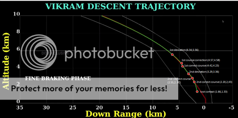
Marked some important points on the graph. Need inputs to add time as secondary axis.