Tejas Mk.2: News & Discussions - 25 February 2018
Re: Tejas Mk.2: News & Discussions - 25 February 2018
Guess what is this..? 
-
ashishvikas
- BRFite
- Posts: 989
- Joined: 17 Oct 2016 14:18
Re: Tejas Mk.2: News & Discussions - 25 February 2018
Final ?JayS wrote:Guess what is this..?
Re: Tejas Mk.2: News & Discussions - 25 February 2018
Made in Amethi GripenJayS wrote:Guess what is this..?
Re: Tejas Mk.2: News & Discussions - 25 February 2018
Finally!! Thank you! Been waiting for so long to see the updated Mk2 configuration with the canards!JayS wrote:Guess what is this..?
Re: Tejas Mk.2: News & Discussions - 25 February 2018
It seems same wing size and shape as that of mk1 and 1m additional length of fuselage.
Last edited by sankum on 08 Oct 2018 00:15, edited 1 time in total.
Re: Tejas Mk.2: News & Discussions - 25 February 2018
Mock-up in AI19 ?
Re: Tejas Mk.2: News & Discussions - 25 February 2018
A few questions arise seeing that picture. I don’t see a probe so is a retractable probe being considered?
Is that a 0.5m fuselage plug or a 1m plug just aft of the cockpit? The shape of the canopy itself seems to be a lot like the thicker chord canopies that we have seen before in some earlier studies.
No wing tip EW pod shown, so will they consider the Mk1A type podded solution? Or is it just that it’ll be a part of other studies being conducted and this was just to finalize the size and placement of the canards?
And are they doing away with the 2 spill ducts from the Mk1 design that took boundary layer turbulent airflow from close to the fuselage and put it onto the top of the wing?
Re: Tejas Mk.2: News & Discussions - 25 February 2018
Also, the vertical stabilator trailing edge sweep seems reversed!
Re: Tejas Mk.2: News & Discussions - 25 February 2018
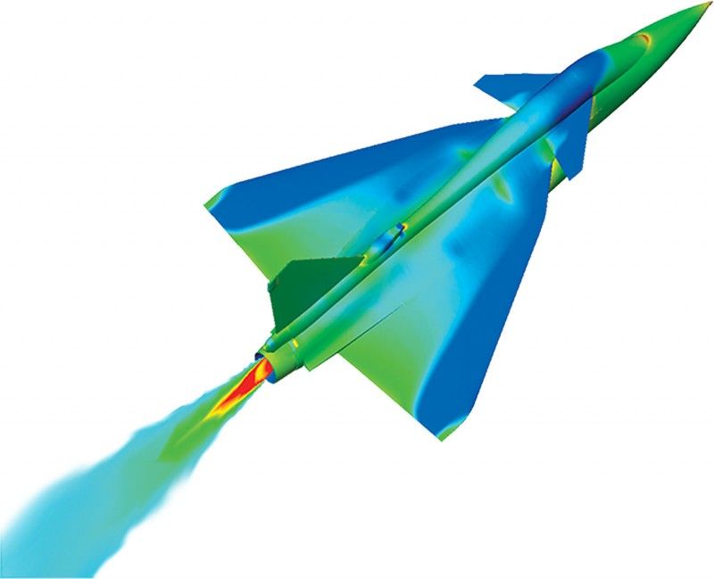
Its CFD post processed contour plot most likely pressure plot. Dont hung up too much on the details like IFR probe, pitot tube or spillways . It may have skipped some. Its from the Canard configuration study I would say. So comparing variouscanard shapes and angles. This particular one might not be the final shape. But close one.
Re: Tejas Mk.2: News & Discussions - 25 February 2018
If you observe carefully, the inlet has moved forward of the wing, so no spill ducts required. Quite a radical redesign from the original. Not sure whether this is a concept study or a design frozen for prototyping. Needless to say, more changes mean more CLAW changes leading to more flight testing.Kartik wrote:And are they doing away with the 2 spill ducts from the Mk1 design that took boundary layer turbulent airflow from close to the fuselage and put it onto the top of the wing?
Re: Tejas Mk.2: News & Discussions - 25 February 2018
My wish is if the fuselage length is incresed by 1m than centre hardpoint must be able to carry 1330 litre EFT just like the innermost hardpoint on wing unlike 720 lt EFT carried on mk1. Two saddle CFT of 2000litre total capacity to free up wing hardpoints.
Re: Tejas Mk.2: News & Discussions - 25 February 2018
If the inlet is moved forward and a canard is added, it leaves a very cramped space for the pilot to climb in. Check how little space is there in Gripen C for the pilot to climb into the cockpit because of the forward inlet and canard mounted on inlet.
http://meldimgxc.pw/Major-Catherine-Lab ... emale.html
http://meldimgxc.pw/Major-Catherine-Lab ... emale.html
Re: Tejas Mk.2: News & Discussions - 25 February 2018
Sarkar sir, couldnt take the eyes of the jordanian lady fighter pilot 
Re: Tejas Mk.2: News & Discussions - 25 February 2018
Many a astute eye. This is close to the final, but not the final. Some details are part of other studies.
Kartik, the canopy is modified (slightly more bulged than the Mk1) to remove the shocks from just aft of the cockpit. They have been reduced a lot, but you can still some of them in this picture. You will here some good news about the wingtip modifications as more info trickles out.
Kartik, the canopy is modified (slightly more bulged than the Mk1) to remove the shocks from just aft of the cockpit. They have been reduced a lot, but you can still some of them in this picture. You will here some good news about the wingtip modifications as more info trickles out.
Re: Tejas Mk.2: News & Discussions - 25 February 2018
When do they start putting together a prototype?
Re: Tejas Mk.2: News & Discussions - 25 February 2018
Indranil Guruji, IOC and FOC requirement will be there afresh for this now? With Canards etc the entire design changed. Right?
Re: Tejas Mk.2: News & Discussions - 25 February 2018
YESKartik wrote:A few questions arise seeing that picture. I don’t see a probe so is a retractable probe being considered?
Re: Tejas Mk.2: News & Discussions - 25 February 2018
I really hope we limit our-self to making a LCA with a larger payload and fuel carrying capacity in MK2.
There is no real need to make it a Indian F16 or EF or Rafale, which can delay induction. FC are the most time consuming of the testing process, no need to make it more difficult for us.
The need of the hour is to speed up induction.
There is no real need to make it a Indian F16 or EF or Rafale, which can delay induction. FC are the most time consuming of the testing process, no need to make it more difficult for us.
The need of the hour is to speed up induction.
Re: Tejas Mk.2: News & Discussions - 25 February 2018
^^^ Exactly. Really concerned that all these changes - canards etc - means it'll have a very long testing cycle and hence delays. Delays result in vicious cycle - users want more advanced capability (stealthy intakes, fly-by-light and other AMCA stuff) - and that would result in more delays and so on.
Just get it out as soon as possible.
Just get it out as soon as possible.
Re: Tejas Mk.2: News & Discussions - 25 February 2018
^ & ^^, IAF has set clear expectations here - they don't want Tejas to be "Light" /PERIOD. For which, Mk1 will be the order.
Mk II, is all about replacing Mig 29s, Mirage 2000 & Jaguar. I'd not be surprised if we have Mk2 which is all about 200 MCAs, as AMCA is delayed, they better get beefed up Mk2 and work with both Mk1a and Mk2 with upgrades till AMCA arrives.
Expect a Mirage 4k kind demo/PV as well as interim to AMCA.
It is not possible to "JUST GET IT OUT!"
Re: Tejas Mk.2: News & Discussions - 25 February 2018
^I think there was a direct quote from IAF which says they want Mk2 to meet Mirage 2000's performance criteria. This is as clear as it gets. We just need to hold IAF to this 10 years down the line.
Re: Tejas Mk.2: News & Discussions - 25 February 2018
They better prepare to keep the production lines for MK1A rolling for more orders on account of inevitable delays in inducting the MK2 with all such major changes.
That will happen for sure.
That will happen for sure.
Re: Tejas Mk.2: News & Discussions - 25 February 2018
Tejas is a on a good path now. If Mk2 is not ready by the time Mk1A production completes, the kind of incremental changes that you guys are suggesting can be incorporated as Mk1B.
Re: Tejas Mk.2: News & Discussions - 25 February 2018
You are seeing things because of the perspective. Only height is increased for better Beta performance.tsarkar wrote:Also, the vertical stabilator trailing edge sweep seems reversed!
Ducts will always be required to spill the boundary layer (if no DSI is used). Instead of spilling it behind the LE, they might spill it on top of it (like in the Rafale). Actually, I am also interested to see how they are going to do this. I had seen some CFD drawings from an year back where the inlet did not extend past the LE. So, I don't know for sure.tsarkar wrote:If you observe carefully, the inlet has moved forward of the wing, so no spill ducts required. Quite a radical redesign from the original. Not sure whether this is a concept study or a design frozen for prototyping. Needless to say, more changes mean more CLAW changes leading to more flight testing.Kartik wrote:And are they doing away with the 2 spill ducts from the Mk1 design that took boundary layer turbulent airflow from close to the fuselage and put it onto the top of the wing?
Special stairs with extended platforms have to be designed.tsarkar wrote:If the inlet is moved forward and a canard is added, it leaves a very cramped space for the pilot to climb in. Check how little space is there in Gripen C for the pilot to climb into the cockpit because of the forward inlet and canard mounted on inlet.
Re: Tejas Mk.2: News & Discussions - 25 February 2018
I like the Rafale design a lot. The blending is superb, a piece of art.Indranil wrote:Ducts will always be required to spill the boundary layer (if no DSI is used). Instead of spilling it behind the LE, they might spill it on top of it (like in the Rafale). Actually, I am also interested to see how they are going to do this. I had seen some CFD drawings from an year back where the inlet did not extend past the LE. So, I don't know for sure.tsarkar wrote: If you observe carefully, the inlet has moved forward of the wing, so no spill ducts required. Quite a radical redesign from the original. Not sure whether this is a concept study or a design frozen for prototyping. Needless to say, more changes mean more CLAW changes leading to more flight testing.
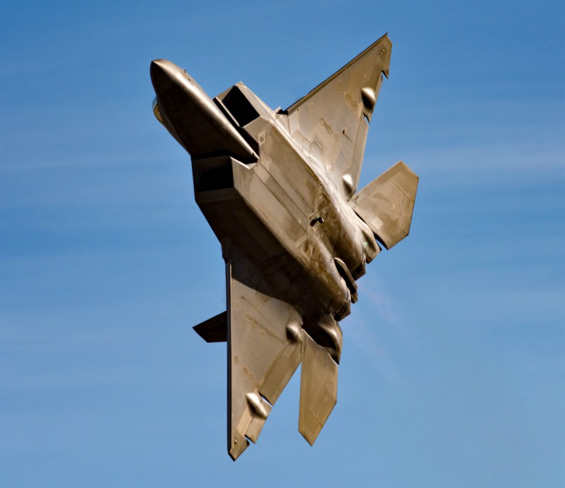
Where does the F22 spill? Couldn't see any duct.
Re: Tejas Mk.2: News & Discussions - 25 February 2018
Everything below the fuselage.
Re: Tejas Mk.2: News & Discussions - 25 February 2018
Ah, ok. Thanks.
Re: Tejas Mk.2: News & Discussions - 25 February 2018
If a splitter plate is used, like the one currently, then ducts won't be required if the inlet is ahead of the wing leading edge. The F/A-18 and Tejas Mk1 use ducts because the inlet is behind and under the wing. If the inlet is ahead of the wing, then a simple splitter plate suffices.Indranil wrote:Ducts will always be required to spill the boundary layer (if no DSI is used). Instead of spilling it behind the LE, they might spill it on top of it (like in the Rafale). Actually, I am also interested to see how they are going to do this. I had seen some CFD drawings from an year back where the inlet did not extend past the LE. So, I don't know for sure.
Re: Tejas Mk.2: News & Discussions - 25 February 2018
I think, we defer in the definition of a "duct". We are saying the same thing.
Re: Tejas Mk.2: News & Discussions - 25 February 2018
Speaking of below the fuselage, any hints on smoothening wing-fuselage blending on the underside?Indranil wrote:Everything below the fuselage.
-
ArjunPandit
- BRF Oldie
- Posts: 4071
- Joined: 29 Mar 2017 06:37
Re: Tejas Mk.2: News & Discussions - 25 February 2018
Fwiw, livefist/Twitter reporting that that order for 46 nlca by 2025
Re: Tejas Mk.2: News & Discussions - 25 February 2018
Tsarkar, pilot climbing on the Tejas mk2 will not be a problem as it will be similar to mk1 as I estimated canard to be 1.5 m in length and total length to be 14.2 m there is still 70 cm gap for pilot to climb in . You can see that in videos of mk1 the stair is towards the front for the pilot to climb in.
The problem will be in trainer version of mk2 that how the pilot will climb in the rear seat without stepping on canard.
The problem will be in trainer version of mk2 that how the pilot will climb in the rear seat without stepping on canard.
Re: Tejas Mk.2: News & Discussions - 25 February 2018
For 2 seater Gripen, there is a split long flat foot plate to gain access to the rear seat.sankum wrote: The problem will be in trainer version of mk2 that how the pilot will climb in the rear seat without stepping on canard.
Check here
https://www.youtube.com/watch?v=J0hq35D ... u.be&t=129
Last edited by Avinandan on 09 Oct 2018 18:59, edited 1 time in total.
Re: Tejas Mk.2: News & Discussions - 25 February 2018
Thanks. For the first time I have seen this.
Re: Tejas Mk.2: News & Discussions - 25 February 2018
LCA already has a huuge draggy wing. Rather than adding canard, perhaps it would be better to adopt AMCA wing design or layout. (without internal bay off course)
Re: Tejas Mk.2: News & Discussions - 25 February 2018
Tejas mk2 is an incremental upgrade over mk1 for minimum gestation period. You are asking for totally new Aircraft.
Re: Tejas Mk.2: News & Discussions - 25 February 2018
Where did you get this from..? And who says canards add to drag..? And how adopting AMCA wing design (basically creating a new aircraft) makes any sense..?Gyan wrote:LCA already has a huuge draggy wing. Rather than adding canard, perhaps it would be better to adopt AMCA wing design or layout. (without internal bay off course)
This is trolling, I say.
Re: Tejas Mk.2: News & Discussions - 25 February 2018
Here is a quote from Indranil ji just a couple of days back on a similar topic. Hope it helps.Gyan wrote:LCA already has a huuge draggy wing. Rather than adding canard, perhaps it would be better to adopt AMCA wing design or layout. (without internal bay off course)
It is not about drag. Yes canards increase frontal area and weight which increase drag, but canards allow you to distribute the wing area more uniformly along the length giving better drag profile for most of the flight envelop. Also at high alpha close coupled canards can decrease L/D ratio by actively controlling vortices over the wing.
At the very beginning, they were studying various combinations: three from within ourselves, one from the French, one from the British and one from the Russians. Out of these, 2 had canards. In the end, they found that they did not need a control canard (like in EF) because the large flaperons were always effective in providing the nose pointing ability. The advantages for the close coupled canard were not significantly higher than 3 active slats and a cranked delta. Also, the cranked delta gives excellent performance in the supersonic domain in the presence of a sideslip. So they decided to go for simplicity given that they were already taking enormous risks. They wanted to keep the FCS simple.
Now, they have a very good handle on the aerodynamics of the LCA and the FCS. So, now they are refining. Mk2 will have canards. They studied 3 configs and chose the best one.
Re: Tejas Mk.2: News & Discussions - 25 February 2018
^^^Again, it seems these queries wrt delta-wing being more-draggy-less-draggy etc tend to keep coming up from time to time - so thought of reproducing one of my very old posts from Jan 2015, which may help people (since it was made as much as possible in lay-man terms) get a perspective of lift-vs-drag etc of a compound delta-wing-design vis-a-vis canards etc ... though that post in itself was more towards LCA design impact on it's turning rates (ITR and STR).
(Note: the linked charts have become non-existent now, I'll try and fix it later - that is, if I'm allowed to edit my posts, later. Must have saved them somewhere)
======================================================================================================================
 of course since not being from the Aero-side of technology, will post a long-pending and half-finished post on a lay-man's take on "turn rates".
But first the disclaimers ...
Disclaimer 1: Aero gurus (like indranilroy, Shalavji, Vinaji, grand-mullah-enquoobuddin (pissBUH), Ramanji et all) nothing to see here, pls ignore this - except for correcting any glaring mistake which is almost inevitable.
Disclaimer 2: I'll try add various charts and references in a day or two - if the forum software allows me to edit my own post after a certain number of days (most probably it won't though).
Anyway, here goes:
(do note a far superior and shorter post from Shalavji on this very aspect is available a few pages back - do read it pls).
At the outset, apologies for a long ramble, but from a lay-man pov, Turn Rates are directly proportional to,
1) Load Factor,
2) Lift Co-eff
3) Air Density
4) but are inversely proportional to Wing Loading
i.e. a High Turn Rate requires Low Wing Loading, high Lift Co-eff and high Load Factor (and higher air density or lower altitude, but this can be taken to be a constant while comparing two diff aircrafts flying at similar altitude etc.)
So let’s examine each of them one by one from LCA perspective:
1) First the Load Factor: Well Load Factor = L/W (L=Lift, W=Weight) - for a all-metal heavy wing (like that of most contemporary fighters) will have a lower load factor compared to lighter all-composite wing like that of a LCA. So heavier wing -> Lower Load Factor, for the same amount of lift -> impacting the turn-rate negatively.
Another way of looking at the load factor is to co-relate with the bank-angle of the turn - simply put cosine of the bank angle = 1/Load Factor. So, for a 60 degree banked turn a load factor of 2 (as Cos 60deg = 0.5), often called a “2 g” turn, is required while the load factor required for 45deg turn is 1.414. Conversely, if the platform is able to withstand a 9G turn, the bank angle achieved (theoretically) would be approx 84deg.
So, if you already have a heavy metallic wing, and add more weight to it by suspending ordinances/fuel-tanks etc, your load factor will go down, allowing you to turn more slowly (lower bank angle). However with a lighter composite wing (with same external weight attached and exact same wing geometry allowing exact same Lift as in the metallic wing case), you reduction in load-factor would be lesser, allowing you to turn quicker (higher bank angle).
The LCA Wing material tech (CFC) wins here, as opposed to myriad of other platforms with metallic wing constructs.
2) Second is the Wind Loading: Wing Loading is nothing but weight of thewing aircraft divided by the wing area. Any delta wing (thus LCA as well) will traditionally have larger area thus wing loading will be lower - however a CFC based light wing as in LCA, provides further advantages towards lowering the wing loading.
Refer to a few pages back to ravi_g's post -
Clean-Wing loading:
LCA -------- J-10 ------- F-18 ------- F-16C
247kg/m² --- 381kg/m² --- 459kg/m² --- 431kg/m²
Thus low-wing-loading design like that in LCA, helps in higher turn-rate compared to even-other delta designs, again because of extensive use of composites.
3) Third is Lift co-eff: Now this is a bit difficult to explain and frankly, it needs to be examined along with the drag co-eff as well. One way is to look at the L-D diagrams where you have 2-D representation of the Lift Co-eff on main axis and the Drag Co-eff on the secondary axis against the angle-of-attack (other is to simply plot the ratio of lift:drag against the AoA or even plot all three together against AoA).
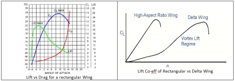
Simply put for a normal rectangular wing plan-form, Lift Co-eff (and of course the Drag Co-eff as well) will increase, quite steeply, with increase in AoA - but upto a point (called Critical AoA), after which with any further increase in AoA the lift co-eff will start reducing (and suddenly, almost at that point, the drag co-eff would start increasing almost exponentially) - net effect the wing will stall.
3a) Diff Load Factors:Before we go further, let's consider another variable, the turn velocity, and two more limits viz. the Structural Load Factor and the Aerodynamic Load Factor ...
Again, simply put, the Aerodynamic Load Factor would limit the turn-rate (due to stall, so governed by Max Lift Coeff) irrespective of amount of structural load (aka Gs) you can still pull. This velocity is called the corner velocity and flight condition where this occurs is the corner point.
So irrespective of how strong the platform is structurally, the max turn-rate you can achieve is limited (Aerodynamic Load Factor) by the Lift Co-eff which in turn is function of the planform geometry of the wing.
3b) Instantaneous and Sustained Turn Rates: The turn-rate you achieve at corner velocity is the Max Instantaneous turn rate (and minm turn radius).
Now let's look at how Lift Coeff comes into play for different wing geometries.
For a rectangular wing planform, the lift co-eff has been explained above - wherein the lift co-eff increases steeply and monotonically with increasing AoA, until a point it stops and starts reducing. But, with a delta plan-form this dipping of Lift Co-eff beyond a certain AoA, doesn't happen at all ... aka, THEORETICALLY, the lift co-eff can continue to increase with increasing AoA.
Thus, again THEORETICALLY, the turn-rate will be higher than that of the normal wing planform design - and so, traditionally the Deltas will have higher Instantaneous turn rate than that of rectangular planform design.
But of course, there's a huge catch - pls wait a minute, and pause for the drag-bhaiya to play it's part as well. The drag co-eff, however will also continue to increase and eventually negate all lift.
So your turn-rates (and thus the Instantaneous turn rates) will be impacted as you would rapidly bleed energy (due to drag) and your turn velocity will start reducing quite dramatically. The only way to negate this drag is to use addn thrust and overcome it and thus maintain/sustain this turning velocity. This is called the sustaining turn rate which obviously is lesser than the pure lift-coeff-influenced-instantaneous turn rate.
Moreover, for a delta wing, because of relatively higher wing area, will have more drag compared to that of a normal wing design i.e. for a delta planform, because of a higher wing area (compared to that of a normal wing geometry) BOTH lift and drag would be higher than that of a normal wing design.
So for a delta planform, the limiting factor for higher turn-rates, is not the lift co-eff so much, but it's the amount of thrust available to overcome this drag that turns out to be the limiting factor - which would mean a higher Instantaneous turn rate (due to higher Lift Co-eff) but a lower Sustained turn rate (due to again higher Drag co-eff) for the deltas, when compared to a rectangular wing design.
But, unfortunately, that's not the end of the story.
3c) The Vortex influence on Lift: Now plane designers are constantly looking at ways and means of increasing lift co-eff while postponing, as much as possible, the corresponding and inevitable drag increase. An "artificial way" of getting this done is to have the flow on the upper surface of a wing rejuvenated/energised by vortex generated upstream.
The energised airflow on the top-surface of the wing provided greater "suction", increasing the lift, without corresponding exponential increase in drag.
This is called postponing the wing-stall.
Now leading edges of a delta are good vortex generators - for any delta wing, all along the leading edge, vortex are generated (until they are unaffected by a phenomena called vortex breakdown) and thus contribute to vortex lift which increases with increase in AoA.
3d) Vortex Burst Limitations: But then again, as with everything else, there's a catch ... vortex getting generated tend to "burst" or destroyed (due to adverse pressure gradients acting on them) resulting in a loss of most of the vortex lift - pls do note vortex bursting is not an issue as long as it can be postponed to a far-enough point downstream to a wing.
And there-in lies the problem ... for a slender delta-wing (aka with high-wing-sweep of say 65deg, found in most modern delta-winged aircraft like Mirage etc) this vortex busting phenomenon is observed to start from around 18deg AoA for a 0.85M flight regime. Increasing the AoA beyond that, the vortex bursting point moves upstream very quickly resulting in abrupt reduction of Lift etc - and about 24deg the wing starts to stall.
3e) The Canard Solution: The TFTA solution to counteract this phenomenon is of course to introduce the close-coupled canard surfaces located just above and forward of the main wing that'll direct airflow downward over the wing. At slow-speed and high AoA it generates vortex which attaches to the upper surface of the wing, stabilising and re-energising the airflow over the wing reducing drag and increasing lift.
3f) Non-Slender Delta planform Impact: But SDREs, being insufferable fools that they are, thought of something else ... how about a non-slender delta (aka with relatively low-wing-sweep of say ~50deg) wing. And like bumbling fools, they soon found out that vortex bursting would onset at a even smaller AoA for a non-slender wing.
But like a true SDRE, they kept their patience to soon found out a phenomenon called flow-reattachment which re-energises the airflow over the wing reducing drag and increasing lift.
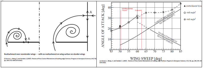
Plus as a bonus, they also found out that vortex breakdown is not a limiting phenomenon as far as the lift force is concerned for non-slender wings - on the contrary, flow reattachment is the key lift-enhancing contributor.
3g)The SDRE LCA Wing Planform: So, they decided to have best of both the worlds ... have a wing which will have both non-slender and slender delta planform. And viola, you got the compound delta LCA wing design, with it's both a low-wing-sweep (50deg, so non-slender delta) and high-wing-sweep (~63deg aka in the "slender delta" territory) as you move from inboard (wing root) to outboard of a wing.
Thus for the relatively lower part of the high-AoA flight regime (say from around 18deg to 22deg etc), the outboard slender delta part of the wing would dutifully contribute to the vortex lift while keeping the drag as low as possible. And with further increase of AoA, as that part of the wing starts to stall due to vortex bursting etc, the inboard non-slender-delta part of the wing will come into play with it's flow-reattachment aspects and keep on further enhancing the lift co-efficient (while still keeping the drag down as low as possible).
So where is the need of any additional control surface like a canard (and thus without the weight and complexity penalty of an additional control surface etc), hain jee?
Of-course, nothing is infinite, and there'll still be a stall angle when the non-slender part of the wing will also give up on flow-reattachment etc, and the whole wing will stall - but then FBW fly-control system will not allow that situation to arise anyway.
===========================================================================================================================
Also do note there's another follow-up excellent post by Indranil on this topic - pls ensure you have gone thru that as well, to get better/full perspective of this issue.
(Note: the linked charts have become non-existent now, I'll try and fix it later - that is, if I'm allowed to edit my posts, later. Must have saved them somewhere)
======================================================================================================================
I'm afraid it seems the discussion over the last couple of pages seems to again be veering towards "feeling" etc ... so I thought I will, with great trepidationindranilroy wrote:I will certainly take you and a few others up on that. It has been on my bucket list for far too long. But it has to wait till something due this May.Karan M wrote: Also, why dont you do a wrietup on the aerodynamics of the LCA? Where you are unsure mark it as such. At least it would serve as huge FAQ versus teh "feelings type" rubbish discussions we tend to engage in on a cyclical basis, having the same claims and same rebuttals.
Rest of us can add on other aspects etc.
But first the disclaimers ...
Disclaimer 1: Aero gurus (like indranilroy, Shalavji, Vinaji, grand-mullah-enquoobuddin (pissBUH), Ramanji et all) nothing to see here, pls ignore this - except for correcting any glaring mistake which is almost inevitable.
Disclaimer 2: I'll try add various charts and references in a day or two - if the forum software allows me to edit my own post after a certain number of days (most probably it won't though).
Anyway, here goes:
(do note a far superior and shorter post from Shalavji on this very aspect is available a few pages back - do read it pls).
At the outset, apologies for a long ramble, but from a lay-man pov, Turn Rates are directly proportional to,
1) Load Factor,
2) Lift Co-eff
3) Air Density
4) but are inversely proportional to Wing Loading
i.e. a High Turn Rate requires Low Wing Loading, high Lift Co-eff and high Load Factor (and higher air density or lower altitude, but this can be taken to be a constant while comparing two diff aircrafts flying at similar altitude etc.)
So let’s examine each of them one by one from LCA perspective:
1) First the Load Factor: Well Load Factor = L/W (L=Lift, W=Weight) - for a all-metal heavy wing (like that of most contemporary fighters) will have a lower load factor compared to lighter all-composite wing like that of a LCA. So heavier wing -> Lower Load Factor, for the same amount of lift -> impacting the turn-rate negatively.
Another way of looking at the load factor is to co-relate with the bank-angle of the turn - simply put cosine of the bank angle = 1/Load Factor. So, for a 60 degree banked turn a load factor of 2 (as Cos 60deg = 0.5), often called a “2 g” turn, is required while the load factor required for 45deg turn is 1.414. Conversely, if the platform is able to withstand a 9G turn, the bank angle achieved (theoretically) would be approx 84deg.
So, if you already have a heavy metallic wing, and add more weight to it by suspending ordinances/fuel-tanks etc, your load factor will go down, allowing you to turn more slowly (lower bank angle). However with a lighter composite wing (with same external weight attached and exact same wing geometry allowing exact same Lift as in the metallic wing case), you reduction in load-factor would be lesser, allowing you to turn quicker (higher bank angle).
The LCA Wing material tech (CFC) wins here, as opposed to myriad of other platforms with metallic wing constructs.
2) Second is the Wind Loading: Wing Loading is nothing but weight of the
Refer to a few pages back to ravi_g's post -
Clean-Wing loading:
LCA -------- J-10 ------- F-18 ------- F-16C
247kg/m² --- 381kg/m² --- 459kg/m² --- 431kg/m²
Thus low-wing-loading design like that in LCA, helps in higher turn-rate compared to even-other delta designs, again because of extensive use of composites.
3) Third is Lift co-eff: Now this is a bit difficult to explain and frankly, it needs to be examined along with the drag co-eff as well. One way is to look at the L-D diagrams where you have 2-D representation of the Lift Co-eff on main axis and the Drag Co-eff on the secondary axis against the angle-of-attack (other is to simply plot the ratio of lift:drag against the AoA or even plot all three together against AoA).

Simply put for a normal rectangular wing plan-form, Lift Co-eff (and of course the Drag Co-eff as well) will increase, quite steeply, with increase in AoA - but upto a point (called Critical AoA), after which with any further increase in AoA the lift co-eff will start reducing (and suddenly, almost at that point, the drag co-eff would start increasing almost exponentially) - net effect the wing will stall.
3a) Diff Load Factors:Before we go further, let's consider another variable, the turn velocity, and two more limits viz. the Structural Load Factor and the Aerodynamic Load Factor ...
Again, simply put, the Aerodynamic Load Factor would limit the turn-rate (due to stall, so governed by Max Lift Coeff) irrespective of amount of structural load (aka Gs) you can still pull. This velocity is called the corner velocity and flight condition where this occurs is the corner point.
So irrespective of how strong the platform is structurally, the max turn-rate you can achieve is limited (Aerodynamic Load Factor) by the Lift Co-eff which in turn is function of the planform geometry of the wing.
3b) Instantaneous and Sustained Turn Rates: The turn-rate you achieve at corner velocity is the Max Instantaneous turn rate (and minm turn radius).
Now let's look at how Lift Coeff comes into play for different wing geometries.
For a rectangular wing planform, the lift co-eff has been explained above - wherein the lift co-eff increases steeply and monotonically with increasing AoA, until a point it stops and starts reducing. But, with a delta plan-form this dipping of Lift Co-eff beyond a certain AoA, doesn't happen at all ... aka, THEORETICALLY, the lift co-eff can continue to increase with increasing AoA.
Thus, again THEORETICALLY, the turn-rate will be higher than that of the normal wing planform design - and so, traditionally the Deltas will have higher Instantaneous turn rate than that of rectangular planform design.
But of course, there's a huge catch - pls wait a minute, and pause for the drag-bhaiya to play it's part as well. The drag co-eff, however will also continue to increase and eventually negate all lift.
So your turn-rates (and thus the Instantaneous turn rates) will be impacted as you would rapidly bleed energy (due to drag) and your turn velocity will start reducing quite dramatically. The only way to negate this drag is to use addn thrust and overcome it and thus maintain/sustain this turning velocity. This is called the sustaining turn rate which obviously is lesser than the pure lift-coeff-influenced-instantaneous turn rate.
Moreover, for a delta wing, because of relatively higher wing area, will have more drag compared to that of a normal wing design i.e. for a delta planform, because of a higher wing area (compared to that of a normal wing geometry) BOTH lift and drag would be higher than that of a normal wing design.
So for a delta planform, the limiting factor for higher turn-rates, is not the lift co-eff so much, but it's the amount of thrust available to overcome this drag that turns out to be the limiting factor - which would mean a higher Instantaneous turn rate (due to higher Lift Co-eff) but a lower Sustained turn rate (due to again higher Drag co-eff) for the deltas, when compared to a rectangular wing design.
But, unfortunately, that's not the end of the story.
3c) The Vortex influence on Lift: Now plane designers are constantly looking at ways and means of increasing lift co-eff while postponing, as much as possible, the corresponding and inevitable drag increase. An "artificial way" of getting this done is to have the flow on the upper surface of a wing rejuvenated/energised by vortex generated upstream.
The energised airflow on the top-surface of the wing provided greater "suction", increasing the lift, without corresponding exponential increase in drag.
This is called postponing the wing-stall.
Now leading edges of a delta are good vortex generators - for any delta wing, all along the leading edge, vortex are generated (until they are unaffected by a phenomena called vortex breakdown) and thus contribute to vortex lift which increases with increase in AoA.
3d) Vortex Burst Limitations: But then again, as with everything else, there's a catch ... vortex getting generated tend to "burst" or destroyed (due to adverse pressure gradients acting on them) resulting in a loss of most of the vortex lift - pls do note vortex bursting is not an issue as long as it can be postponed to a far-enough point downstream to a wing.
And there-in lies the problem ... for a slender delta-wing (aka with high-wing-sweep of say 65deg, found in most modern delta-winged aircraft like Mirage etc) this vortex busting phenomenon is observed to start from around 18deg AoA for a 0.85M flight regime. Increasing the AoA beyond that, the vortex bursting point moves upstream very quickly resulting in abrupt reduction of Lift etc - and about 24deg the wing starts to stall.
3e) The Canard Solution: The TFTA solution to counteract this phenomenon is of course to introduce the close-coupled canard surfaces located just above and forward of the main wing that'll direct airflow downward over the wing. At slow-speed and high AoA it generates vortex which attaches to the upper surface of the wing, stabilising and re-energising the airflow over the wing reducing drag and increasing lift.
3f) Non-Slender Delta planform Impact: But SDREs, being insufferable fools that they are, thought of something else ... how about a non-slender delta (aka with relatively low-wing-sweep of say ~50deg) wing. And like bumbling fools, they soon found out that vortex bursting would onset at a even smaller AoA for a non-slender wing.
But like a true SDRE, they kept their patience to soon found out a phenomenon called flow-reattachment which re-energises the airflow over the wing reducing drag and increasing lift.

Plus as a bonus, they also found out that vortex breakdown is not a limiting phenomenon as far as the lift force is concerned for non-slender wings - on the contrary, flow reattachment is the key lift-enhancing contributor.
3g)The SDRE LCA Wing Planform: So, they decided to have best of both the worlds ... have a wing which will have both non-slender and slender delta planform. And viola, you got the compound delta LCA wing design, with it's both a low-wing-sweep (50deg, so non-slender delta) and high-wing-sweep (~63deg aka in the "slender delta" territory) as you move from inboard (wing root) to outboard of a wing.
Thus for the relatively lower part of the high-AoA flight regime (say from around 18deg to 22deg etc), the outboard slender delta part of the wing would dutifully contribute to the vortex lift while keeping the drag as low as possible. And with further increase of AoA, as that part of the wing starts to stall due to vortex bursting etc, the inboard non-slender-delta part of the wing will come into play with it's flow-reattachment aspects and keep on further enhancing the lift co-efficient (while still keeping the drag down as low as possible).
So where is the need of any additional control surface like a canard (and thus without the weight and complexity penalty of an additional control surface etc), hain jee?
Of-course, nothing is infinite, and there'll still be a stall angle when the non-slender part of the wing will also give up on flow-reattachment etc, and the whole wing will stall - but then FBW fly-control system will not allow that situation to arise anyway.
===========================================================================================================================
Also do note there's another follow-up excellent post by Indranil on this topic - pls ensure you have gone thru that as well, to get better/full perspective of this issue.