Design Your Own Space Launch vehicle
Design Your Own Space Launch vehicle
I'll be damned if I know anything about this subject, but someone please do the honours and cross post earlier posts here.
-
vina
- BRF Oldie
- Posts: 6046
- Joined: 11 May 2005 06:56
- Location: Doing Nijikaran, Udharikaran and Baazarikaran to Commies and Assorted Leftists
Re: Design Your Own Space Launch vehicle
Ok folks. Lets get started ! As a starting point do the following
1) Examine the design of GSLV MK1/2 and see why it falls well short of it's potential , when compared to it's analogs elsewhere (Ariane 4 and LM3B) which are comparable in size and underlying technology. Lets see what were the design choices made that led to this and what the fixes for that are.
2) Let us examine the configuration and the specs of LVM3 /GSLV MK3, what it's max performance will be , what is it's growth potential , and how it compares with it's analogs flying elsewhere and how flexible is it going forward .
Now this exercise to be of any use CANNOT be some random "flight of fancy" based on "I think" / " I feel" . To paraphrase NR Narayanamurthy (even if he possibly might not the one who create it, I first heard it from him) ,
As mortals, whatever assertion we make has to be based on facts , science and sound engineering principles. So, as a start, I had created a spreadsheet model of the GSLV D6 based on the launch brochure and the data available in it and the published weights, propellant loadings and other data that I picked up from the plethora of excellent space enthusiast websites that have some incredibly detailed info about the Indian space launch vehicles and using fundamentals of rocketry tried to find answers to a) Why is the MK1/2 lugging 28 tons for nearly 45 seconds b) Why is there such a big performance difference between the MK1/2 and it's analogs. I did put up the answers in the original thread, but unfortunately that place degenerated into a "Space Nukkad" , and here we are.
I will put up the spread sheet for everyone to play with in due course, I first need to reformat it,put in a lot of comments and explanatory notes and generally tidy it up before anyone else can sense of it and use it. I put that together in my spare time in less than 30 minutes. However don't hold my feet to the fire for a timeline, I will try to put it up as soon as I can, time permitting.
Once we have played around with it and got good answers on details on the Mk1/2 , let us do the same for GSLV MKIII ( I am downloading the launch brochure of LVM3/Care in another tab as I am typing it out) and we hopefully can get some insights on any questions that we might come up with. In fact, in the MK1 exercise, there were a few great questions that got answered including the following 1) Why are they lugging 28 tons of deadweight AND burning 40 tons of fuel in doing so. Why not drop it right away ? 2) Can the GSLV do 4 tons ? 3) Can it do 6 tons ? and that gave insights. Similar questions on GSLV MKIII too could have surprising answers, which will be based on facts and science.
1) Examine the design of GSLV MK1/2 and see why it falls well short of it's potential , when compared to it's analogs elsewhere (Ariane 4 and LM3B) which are comparable in size and underlying technology. Lets see what were the design choices made that led to this and what the fixes for that are.
2) Let us examine the configuration and the specs of LVM3 /GSLV MK3, what it's max performance will be , what is it's growth potential , and how it compares with it's analogs flying elsewhere and how flexible is it going forward .
Now this exercise to be of any use CANNOT be some random "flight of fancy" based on "I think" / " I feel" . To paraphrase NR Narayanamurthy (even if he possibly might not the one who create it, I first heard it from him) ,
In God we Trust. Everyone else brings data
As mortals, whatever assertion we make has to be based on facts , science and sound engineering principles. So, as a start, I had created a spreadsheet model of the GSLV D6 based on the launch brochure and the data available in it and the published weights, propellant loadings and other data that I picked up from the plethora of excellent space enthusiast websites that have some incredibly detailed info about the Indian space launch vehicles and using fundamentals of rocketry tried to find answers to a) Why is the MK1/2 lugging 28 tons for nearly 45 seconds b) Why is there such a big performance difference between the MK1/2 and it's analogs. I did put up the answers in the original thread, but unfortunately that place degenerated into a "Space Nukkad" , and here we are.
I will put up the spread sheet for everyone to play with in due course, I first need to reformat it,put in a lot of comments and explanatory notes and generally tidy it up before anyone else can sense of it and use it. I put that together in my spare time in less than 30 minutes. However don't hold my feet to the fire for a timeline, I will try to put it up as soon as I can, time permitting.
Once we have played around with it and got good answers on details on the Mk1/2 , let us do the same for GSLV MKIII ( I am downloading the launch brochure of LVM3/Care in another tab as I am typing it out) and we hopefully can get some insights on any questions that we might come up with. In fact, in the MK1 exercise, there were a few great questions that got answered including the following 1) Why are they lugging 28 tons of deadweight AND burning 40 tons of fuel in doing so. Why not drop it right away ? 2) Can the GSLV do 4 tons ? 3) Can it do 6 tons ? and that gave insights. Similar questions on GSLV MKIII too could have surprising answers, which will be based on facts and science.
Re: Design Your Own Space Launch vehicle
^^^
Very thankful for the idea to share the worksheet.
I am noway connected with Launch vehicle but love to play around working on unknowns.
Very thankful for the idea to share the worksheet.
I am noway connected with Launch vehicle but love to play around working on unknowns.
Re: Design Your Own Space Launch vehicle
thread need to be encouraged, may be a thread should be there for Tejas too
Re: Design Your Own Space Launch vehicle
I would like to plug one of my questions here.
indranilroy wrote:Continuing with the back of the envelop calculations. Vina could you use your spreadsheets to calculate the values of payloads x, y and z. I am trying to find the performance of a 3.2 m dia GSLV-H using parts that are available today S200 and CE-20. I have kept the weight of stage 2 + stage 3 the same as the current GSLV MK2, as it has to be powered by the same engine. Stage 1 is obviously heavier by virtue of the S200.
GSLV-H1 (H is for hypothetical, not heavy)
Synopsis:
1. S-200 as Stage 1
2. Stage 2 dia changed to 3.2 mtrs, propellant mass left unchanged
==========================================================
Height: ~48 mtrs
Diameter: 3.2 mtrs
Launch mass: 490 + x T
payload: x T
1st stage (S200)
=============
Length : 22 m
Diameter : 3.2 m
Inert Mass 31.3 T
Launch Mass : 238 T
Thrust (SL): 5,151 kN
Specific Impulse (SL): 227s
Specific Impulse (Vac): 274.5s
Stage ignition: T0 + 0 secs
Burn Time: 130s
Separation: 149.5s
Boosters 4 (current config as GSLV)
===========
Length: 19.7m
Diameter: 2.1m
Inert Mass: 5.6 k T
Launch Mass: 47.6 T
Thrust (SL): 763kN
Impulse: 293 sec
Stage ignition: T0 - 4.8 secs
Burn Time: 153.8 sec v(flight time of 149 secs)
Stage Separation: With Core Stage
2nd stage (same fuel-mass/engine as GSLV)
========================================================
Inert Mass: ~5.5 T (near identical to GSLV)
Launch Mass: 45 T (near identical to GSLV)
Length: ~ 9.64m (tank with 3.2 mtr diameter with same volume as GSLV stage 2 tank, engine length is 3.51 mtr)
Diameter: 3.2m
Propellant Mass: 39,400kg
Propulsion: 1 Vikas 4
Thrust (Vac): 799kN
Impulse: 293s
Engine Dry Weight: 900kg
Stage ignition: T0 + 149.5 secs
Burn Time: 141 sec
Stage seperation: T0 + 293 secs
3rd stage (same fuel-mass/engine as GSLV)
==============================
Inert Mass: ~2.5 T (near identical to GSLV)
Launch Mass: ~15.3 T (near identical to GSLV)
Length: ~ 7.2m (tank with 3.2 mtr diameter with same volume as GSLV stage 3 tank, engine length is 2.15 mtr)
Diameter: 3.2 m
Propellant Mass: 12.8 T
Propulsion: 1 ICE (CE-7.5)
Thrust (Vac): 73.5 to 93.1kN
Specific Impulse: (Vac): 454s
Burn Time Up to: 1,000sec
Payload fairing
=============
Length 7.8 m
Mass ~ 0.5 T (including adapters etc.)
+++++++++++++++++++++++++++++++++++++++++++++++++++++++
GSLV-H2 (H is for hypothetical, not heavy)
Synopsis: S-200 + stage 2 and stage 3 dia changed to 3.2 mtrs, propellant mass of stage 2 and stage 3 left unchanged, stage 3 is now powered by CE-20
===================================
height: ~49 mtrs
Diameter: 3.2 mtrs
launch mass: 490 + y T
payload: y T
1st stage (S200)
=============
Length : 22 m
Diameter : 3.2 m
Inert Mass 31.3 T
Launch Mass : 238 T
Thrust (SL): 5,151 kN
Specific Impulse (SL): 227s
Specific Impulse (Vac): 274.5s
Stage ignition: T0 + 0 secs
Burn Time: 130s
Separation: 149.5s
Boosters 4 (current config as GSLV)
===========
Length: 19.7m
Diameter: 2.1m
Inert Mass: 5.6 k T
Launch Mass: 47.6 T
Thrust (SL): 763kN
Impulse: 293 sec
Stage ignition: T0 - 4.8 secs
Burn Time: 153.8 sec v(flight time of 149 secs)
Stage Separation: With Core Stage
2nd stage (same fuel-mass/engine as GSLV)
============================================
Inert Mass: ~5.5 T (near identical to GSLV)
Launch Mass: 45 T (near identical to GSLV)
Length: ~ 9.64m (tank with 3.2 mtr diameter with same volume as GSLV stage 2 tank, engine length is 3.51 mtr)
Diameter: 3.2m
Propellant Mass: 39,400kg
Propulsion: 1 Vikas 4
Thrust (Vac): 799kN
Impulse: 293s
Engine Dry Weight: 900kg
Stage ignition: T0 + 149.5 secs
Burn Time: 141 sec
Stage seperation: T0 + 293 secs
3rd stage (same fuel-mass/engine as GSLV)
==============================
Inert Mass: ~2.5 T (near identical to GSLV)
Launch Mass: ~15.3 T (near identical to GSLV)
Length: ~ 8.2m (added 1 mtr extra for the CE-20 engine)
Diameter: 3.2 m
Propellant Mass: 12.8 T
Propulsion: 1 CE-20
Thrust – Vacuum: 200kN
Operational Range: 180-220kN
Specific Impulse (Vac): 443s
Burn Time: 297 secs
Payload fairing
=============
Length 7.8 m
Mass ~ 0.5 T (including adapters etc.)
++++++++++++++++++++++++++++++++++++++++++++++++++++
GSLV-H3 (H is for hypothetical, not heavy)
Synopsis: S-200 + stage 2 and stage 3 dia changed to 3.2 mtrs, propellant mass of stage 3 increased to propellant mass of LVM3, propellant mass of stage 2 decreased accordingly, total mass of propellant in Stage 2 + stage 3 is still identical GSLV -Mk2, stage 3 is powered by CE-20
===================================
height: ~52 mtrs
Diameter: 3.2 mtrs
launch mass: 490 + z T
payload: z T
1st stage (S200)
=============
Length : 22 m
Diameter : 3.2 m
Inert Mass 31.3 T
Launch Mass : 238 T
Thrust (SL): 5,151 kN
Specific Impulse (SL): 227s
Specific Impulse (Vac): 274.5s
Stage ignition: T0 + 0 secs
Burn Time: 130s
Separation: 149.5s
Boosters 4 (current config as GSLV)
===========
Length: 19.7m
Diameter: 2.1m
Inert Mass: 5.6 k T
Launch Mass: 47.6 T
Thrust (SL): 763kN
Impulse: 293 sec
Stage ignition: T0 - 4.8 secs
Burn Time: 153.8 sec v(flight time of 149 secs)
Stage Separation: With Core Stage
2nd stage (shortened to allow a longer Stage 3)
=====================================================
Inert Mass: ~5 T
Launch Mass: 31 T
Length: ~ 7.5 m
Diameter: 3.2m
Propellant Mass: 26 T
Propulsion: 1 Vikas 4
Thrust (Vac): 799kN
Impulse: 293s
Stage ignition: T0 + 149.5 secs
Burn Time: 91.5 sec
Stage seperation: T0 + 243 secs
3rd stage
==============================
Inert Mass: ~4.0 T (same mass as C25 on LVM3)
Launch Mass: ~29.0 T (same mass as C25 on LVM3)
Length: ~ 13.0m (same volume as LVM3 tank, engine length is 3.15 mtr)
Diameter: 3.2 m
Propellant Mass: 25.0 T
Propulsion: 1 CE-20
Thrust – Vacuum: 200kN
Operational Range: 180-220kN
Specific Impulse (Vac): 443s
Burn Time: 590 secs
Payload fairing
=============
Length 7.8 m
Mass ~ 0.5 T (including adapters etc.)
-
vina
- BRF Oldie
- Posts: 6046
- Joined: 11 May 2005 06:56
- Location: Doing Nijikaran, Udharikaran and Baazarikaran to Commies and Assorted Leftists
Re: Design Your Own Space Launch vehicle
From what I gather, gravity drag will vary based on the flight path flown and of course as well as the weight. Air drag of course is shape and dimension dependent , and indeed the flight path as well. The way they analyse this is a reduction in the delta V from the theoretical and the is largely a parameter based thing. There is no "analytical" close form solution , and if at all there is , you will have to plug it in and solve it numerically. Like much of engineering, these these are made non dimensional and published as charts. If you are doing a clean sheet design, you would use those charts. Look up MIT Open Course ware and there is a couple of basic introductory stuff, along with a few charts for this.adityadange wrote:@vina, just a question.
does gravity drag remains constant for all size/shape/weight objects? reason i ask this question is, the four configs you have mentioned above will have different weight (and probably size/shape if we differentiate them as clustered and non clustered configs). If gravity drag varies based on dimensions then calculations may show wrong output. or this aspect is already taken care in your spreadsheet?
The thumb rule for this seems to around 1Km/s loss in delta V as the penalty.
Coming back to simulation of GSLV D6 like I did, we have a much easier task. We have ACTUAL flight data , and we know how the vehicle is performing in the real world. All you need to do is adjust the realised specific impulse per stage so that you have adjusted for all the drag (air, gravity, difference between vacuum IsP and the actual Isp realised for the duration of the flight etc) losses the vehicle will experience , so since we delta V at each rocket event and the propellant burn, it is easy to use estimate the actual performance of the motors in terms of Actual realised Isp . This will of course be lower than the theoretical values and you use the derived Isp , when you calculate what the performance will be when you change the configuration.
If you keep the overall mass of the vehicle within a narrow range of what the original GSLV D6 had, you can't be far off. Also, you need to make sure that the velocity profile when you fiddle around should be around the same as the original vehicle, and take into constraints like the 800KN engine in the 2nd stage and if you need to maintain a t:w ratio of 1:1 or better in the remaining vehicle. If these two are taken care of, you are flying a very REAL vehicle. Your Max Q (max. dynamic pressure) will be exactly similar to the original vehicle (since your velocity profile is same and everything else, including overall mass is nearly same) . You end up with a pretty good high fidelity model .
From here, you can do the "what ifs" very easily. For e.g., if you ask the question what will happen if I drop the the entire 1st stage at 109 seconds and load only 30 tons of fuel in the L40 ? or what if we cluster the liquids in the core and if we had solids as boosters (in that case, you just drop the solids and keep burning the liquids until whatever).. Or if you decide you want a longer burn on the core and load 10 more tons ? These will be very easy to do and of course , consistent .
By that, if you are making comparisons between config 1 and config 2, and want to find the difference, as long as your underlying assumptions (e.g., I will leave 1 ton balance fuel in the GS2 tank, or my CUS will have 50kgs fuel left at cutoff etc), you will end up with answers that are correct.
-
vina
- BRF Oldie
- Posts: 6046
- Joined: 11 May 2005 06:56
- Location: Doing Nijikaran, Udharikaran and Baazarikaran to Commies and Assorted Leftists
Re: Design Your Own Space Launch vehicle
Also, while doing the model, I came across an answer to a very interesting questions. During the launch videos we see, we always see the call out of "Closed Loop Guidance" engaging. As a kid when I went to SHAR for an SLV3 launch during the early 80s, ISRO Folks explained to me that the SLV 3 was just a "point and shoot" and cannot correct for deviations and had an "Open Loop" guidance. The closed loop guidance was introduced in ASLV and indeed , all vehicles (I notice irrespective of origin) , typically have open loop in the lower stages and the closed loop kicks off only later in the flight.
One would think that it makes sense to have a tight feedback control loop guidance to correct for errors right from the beginning. When one does the numbers and models things, It turns out, that is not done for a very good reason. That is, it is efficient to use gravity to turn the launch vehicle to pitch it over and use it to keep it pitching over and follow an optimum trajectory.
Check out Gravity Turn or zero lift turn. The trick it seems is to keep the angle of attack of the vehicle to zero during the gravity assisted following of the optimal path (this avoids oversized loads on the vehicle, especially in the lower stage when it is heaviest) . At this stage, correcting for drift would introduce an angle of attack and they don't bother. In later stages, when the vehicle gets lighter, it is structurally less costly to do it and they do it. Wiki quotes the British Black Arrow, as not having trajectory correction. Our own SLV 3 too had only open loop guidance.
It is also interesting that the exact same Physics is used in descent (and also ascent) to and from moon and other plants as well. Cool! You get to know these things (outside a formal classroom) by yourself only when you model these and it is pretty easy to do so.
-
prasannasimha
- Forum Moderator
- Posts: 1214
- Joined: 15 Aug 2016 00:22
Re: Design Your Own Space Launch vehicle
Have you factored in the coasting phase when you calculated the 40 second lugging . I think you need to checkout the velocity height profile because in some of the flights they have allowed the vehicle to actually descend assisted by gravity to increase velocity during coasting followed by next stage firing.
Re: Design Your Own Space Launch vehicle
The coasting phase is after the second stage burnout. Lugging of the empty S139 is before separation of 1st stage.
-
prasannasimha
- Forum Moderator
- Posts: 1214
- Joined: 15 Aug 2016 00:22
Re: Design Your Own Space Launch vehicle
^ Oops my error.
-
vina
- BRF Oldie
- Posts: 6046
- Joined: 11 May 2005 06:56
- Location: Doing Nijikaran, Udharikaran and Baazarikaran to Commies and Assorted Leftists
Re: Design Your Own Space Launch vehicle
Yes. Exactly. However note, coasting during the boost stages (or indeed any stage) before getting to orbit is sub optimal. ( I will post reasons why it is so later, you can google it up or simply play around with the rocket equation between a coast and no coast scenario) , and you wont do a coast at all, unless you have EXTREMELY good reasons to do so.indranilroy wrote:The coasting phase is after the second stage burnout. Lugging of the empty S139 is before separation of 1st stage.
-
vina
- BRF Oldie
- Posts: 6046
- Joined: 11 May 2005 06:56
- Location: Doing Nijikaran, Udharikaran and Baazarikaran to Commies and Assorted Leftists
Re: Design Your Own Space Launch vehicle
Interesting thing I noticed about LVM / GSLV MKIII design. The two solid boosters burn out at 130 seconds and are discarded only at 149 seconds. The empty casing of the S200 is 31.3 tons. So GSVL MKIII is carrying 60 tons dead weight for 19 seconds. It will be interesting to find out why. This is a clean sheet design and they could drop the spent casings immediately if needed ,but choose to carry it and this too when the L110 stage has already been lit some 35 seconds earlier and if they dropped it after around 5 to 6 seconds or so after L110 ignition (that is about the time the L110 take to get to full thrust), there should be enough steering and control forces available for the vehicle. I think we will get some interesting insights on that when we model it.
Can someone see if in the LVM3 launch video if the English commentator Dr Radhakrishnan (a very knowledgable man, who obviously knows his stuff) talks about when Max Q (i.e. max dynamic pressure) is reached for MKIII?
Can someone see if in the LVM3 launch video if the English commentator Dr Radhakrishnan (a very knowledgable man, who obviously knows his stuff) talks about when Max Q (i.e. max dynamic pressure) is reached for MKIII?
Last edited by vina on 26 Sep 2016 23:54, edited 1 time in total.
-
vina
- BRF Oldie
- Posts: 6046
- Joined: 11 May 2005 06:56
- Location: Doing Nijikaran, Udharikaran and Baazarikaran to Commies and Assorted Leftists
Re: Design Your Own Space Launch vehicle
In all the configs, we have where you replaced the S139 with S200, it still wont work. The S200 has a burn time of 130 seconds and at that point, the vehicle would have put on a deltaV of around 1900 m/s . If they dropped the S200+ 4 L40 this point, the remaining vehicle (2nd + 3rd stage) would be around 86.2 tons, which would be higher than the thrust of the GS2 motor which is around 80 tons in vacuum and the t:w ratio would be less than 1.indranilroy wrote:Continuing with the back of the envelop calculations. Vina could you use your spreadsheets to calculate the values of payloads x, y and z
You need a velocity of around 2400m/s at the start of the 2nd stage , so that the remaining 2 stages put an additional 7.8 km/s of delta V and put the satellite in orbit. So all the configs you propose wont work.
Re: Design Your Own Space Launch vehicle
I made sure that the second+third stage has identical weights as the current GSLV Mk2.vina wrote:In all the configs, we have where you replaced the S139 with S200, it still wont work. The S200 has a burn time of 130 seconds and at that point, the vehicle would have put on a deltaV of around 1900 m/s . If they dropped the S200+ 4 L40 this point, the remaining vehicle (2nd + 3rd stage) would be around 86.2 tons, which would be higher than the thrust of the GS2 motor which is around 80 tons in vacuum and the t:w ratio would be less than 1.indranilroy wrote:Continuing with the back of the envelop calculations. Vina could you use your spreadsheets to calculate the values of payloads x, y and z
You need a velocity of around 2400m/s at the start of the 2nd stage , so that the remaining 2 stages put an additional 7.8 km/s of delta V and put the satellite in orbit. So all the configs you propose wont work.
Config 1: 45 T (second stage) + 15.3 T (third stage) + payload* = 60.3 T + payload mass.
Config 2: 45 T (second stage) + 15.3 T (third stage) + payload* = 60.3 T + payload mass.
Config 3: 31 T (second stage) + 29.0 T (third stage) + payload* = 60 T + payload mass.
* payload fairings and adapters weight extra.
I have kept the first stage operation and separation sequence identical to the current GSLV as well.
Code: Select all
  -4.8 secs: Booster ignition
   0.0 secs: 1st stage (S200) ignition
+130.0 secs: 1st stage burnout
+149.0 secs: Booster burnout
+149.0 secs: 2nd stage ignition
+149.5 secs: 1st stage separation
-
vina
- BRF Oldie
- Posts: 6046
- Joined: 11 May 2005 06:56
- Location: Doing Nijikaran, Udharikaran and Baazarikaran to Commies and Assorted Leftists
Re: Design Your Own Space Launch vehicle
Yes, however, what was an error was the lift of mass of 490 tons (487 tons to be exact). The L40 stages in this case can be topped to a max of 35 tons only (to sync with the S200) burn out. So the lift of mass is 20 tons (i.e. 467 tons) less. So if we plug in 467 tons in the spreadsheet with the rest of the numbers, you get this.indranilroy wrote:I made sure that the second+third stage has identical weights as the current GSLV Mk2.
The throw weight to GTO is around 4 tons (with 2.5 tons being the inert mass of the CE 12 and some 500 kg for payload adapter etc) . So yeah, if you replace the S139 with S200 in the core of GSLV Mk2 and you drop the entire stage ( S200 + 4 L 40s which are loaded with 35 tons of fuel each at lift off), you have a vehicle with 4.2 Tons to GTO! . So this is a "easy" fix.
Notice however, that this is there is no ROOM for growth beyond 4 tons to say 6 tons. The vehicle is still 300 m/s "short" of ideal conditions of around 2400 km/s (for the GS2+ CUS combo) at GS2 ignition for current components (GS2 and CE 12) as is.
Wont work. I plugged numbers into the spreadsheet now at lunch time . The vehicle mass at GS2 will be 87.6 tons. So yeah, there is really no room for growth.
Re: Design Your Own Space Launch vehicle
I'm not sure if you've already accounted for this, but it has been on my mind for a while ...
I remembered reading that the Space Shuttle main engine throttles down after a while to decrease stress. I checked it up on the wiki and sure enough it does and it also points to something called Max Q (I'm afraid I'm way out of my depth here). Could that be the reason why Mk3 doesn't light up the Vikas engine on the ground ?
I remembered reading that the Space Shuttle main engine throttles down after a while to decrease stress. I checked it up on the wiki and sure enough it does and it also points to something called Max Q (I'm afraid I'm way out of my depth here). Could that be the reason why Mk3 doesn't light up the Vikas engine on the ground ?
Re: Design Your Own Space Launch vehicle
No, this is not part of the Vina's model as far I can tell. He has not considered any structural loads. If you listen to the commentary of PSLV and GSLV launches, they call out Max Q. However, I don't think that this is the limiting feature here. Afterall, the L110s can be throttled down around max Q (which would have arrived earlier if the L110 was started on the ground). Also look at the Ariane 5, which ignites the boosters and the core stage from ground. In a clean sheet design, this can be handled.
The reason why they are going for solid rockets is because their specific impulse is very close to that of the liquid engines at sea level (, and therefore, not much would be gained by firing the L110s on the ground. However, if this fuel is preserved till the vehicle reaches the upper atmosphere (40 km), where the gains from a liquid engine becomes significant, then the gains are more significant. I am waiting for geethji's reply on the space discussion thread, as to why the boosters stay connected for 20 seconds extra. It does not make any sense. I think that was only because of the experimental nature of the first flight. They even tested sending the engine turn off commands to the dummy third stage.
The drawback of the LVM-3 is that as it stands today, it cannot work without the large S200 boosters. Once the SC160 comes on board, ISRO will be able to play around with different boosters to cater to different payloads between 1.5-6.5 T to GTO. But that won't be till near 2020.
Re: Design Your Own Space Launch vehicle
From ISRO brochures
Could someone explain what is carried for 20 seconds
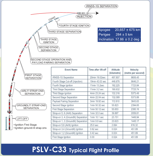
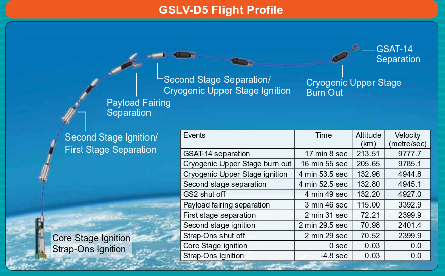
Could someone explain what is carried for 20 seconds


-
vina
- BRF Oldie
- Posts: 6046
- Joined: 11 May 2005 06:56
- Location: Doing Nijikaran, Udharikaran and Baazarikaran to Commies and Assorted Leftists
Re: Design Your Own Space Launch vehicle
For folks who are interested, actually, let us look back to pages 35, 36 and 37 on the "Indian Space Thread". All the issues we are backing up with number had been debated earlier . And again the same "thinkers" and "feelers", put the exact same arguments, including on "CG" and "Cp" etc.
I had explained back then, how a solid engine actually works (so if a rocket has just a single stage, made of a solid engine, and as the engine burns, does the CG move upwards?) , what is parallel staging, what is tandem staging , what is ullage, etc . etc.
Also included was a "guess" on a quick fix on what was possible for MK2 (without numbers).
viewtopic.php?f=3&t=6652&start=1360#p1764171
viewtopic.php?f=3&t=6652&start=1360#p1764222
I wonder where sane posters like "KrishG" went. Here was one person who clearly knew and identified the issue with MK2.
His response is viewtopic.php?f=3&t=6652&start=1360#p1764222 .
And a further response from him. viewtopic.php?f=3&t=6652&start=1360#p1764222
Here are some of the "think" and "feel" responses along the usual lines. "vina is bad mouthing ISRO", "vina thinks Von Braun was dumb" . Now that "everyone knows that MKII is sub optimal" (they didn't in page 35 to 37 though), to "vina is beating ISRO/India/Indians with a Stump" .. It is the same story..
Here is that post viewtopic.php?f=3&t=6652&start=1360#p1764222 and right after that is my response.
And let me quote one part of my response ,from 2014!
"Ok. The designs you are putting up. Will they fly stably?"
My post on staging, how it works, etc. viewtopic.php?f=3&t=6652&start=1440#p1766329
I had explained back then, how a solid engine actually works (so if a rocket has just a single stage, made of a solid engine, and as the engine burns, does the CG move upwards?) , what is parallel staging, what is tandem staging , what is ullage, etc . etc.
Also included was a "guess" on a quick fix on what was possible for MK2 (without numbers).
viewtopic.php?f=3&t=6652&start=1360#p1764171
viewtopic.php?f=3&t=6652&start=1360#p1764222
I wonder where sane posters like "KrishG" went. Here was one person who clearly knew and identified the issue with MK2.
His response is viewtopic.php?f=3&t=6652&start=1360#p1764222 .
And a further response from him. viewtopic.php?f=3&t=6652&start=1360#p1764222
Here are some of the "think" and "feel" responses along the usual lines. "vina is bad mouthing ISRO", "vina thinks Von Braun was dumb" . Now that "everyone knows that MKII is sub optimal" (they didn't in page 35 to 37 though), to "vina is beating ISRO/India/Indians with a Stump" .. It is the same story..
Here is that post viewtopic.php?f=3&t=6652&start=1360#p1764222 and right after that is my response.
And let me quote one part of my response ,from 2014!
The reason why I am posting it is this has stuff about CG and Cp , "airlit boosters" / whatever and will answer questions such as .Now, if those questions are actually answered, we can have a sane discussion based on Physics/Reality/Facts, rather than Vina must be "theoretical" , Von Braun must be dumb, Vina said ISRO engineers were dumb kind of nonsense.
"Ok. The designs you are putting up. Will they fly stably?"
My post on staging, how it works, etc. viewtopic.php?f=3&t=6652&start=1440#p1766329
-
vina
- BRF Oldie
- Posts: 6046
- Joined: 11 May 2005 06:56
- Location: Doing Nijikaran, Udharikaran and Baazarikaran to Commies and Assorted Leftists
Re: Design Your Own Space Launch vehicle
Yes. I have accounted for MaxQ ! How, because ISRO did, and I flew my math model rocket using the flight data!.srin wrote:I'm not sure if you've already accounted for this, but it has been on my mind for a while ...
I remembered reading that the Space Shuttle main engine throttles down after a while to decrease stress. I checked it up on the wiki and sure enough it does and it also points to something called Max Q (I'm afraid I'm way out of my depth here). Could that be the reason why Mk3 doesn't light up the Vikas engine on the ground ?
BTW, in addition to the liquid engines throttling down, the solids in the shuttle (and of course in the PSVL, GSLV) throttle down as well . How is that possible. We all know that solids cannot be throttled!! The trick is in the grain design. Different patterns have different burn rates and the solids are designed to have an "M", shaped thrust vs time profile. That is High thrust at take off, and then falling off at around Max Q so that the vehicle is within structural design limits and then raise the thrust again soon after so that it accelerates away quickly.
So, in many ways, a booster such as S139 or S200 would have a tailored profile and it is not a generic bolt on for any vehicle, but rather should be in many cases tailored. It is addressed during making the solid stage and is not that difficult. However, you cannot make it in bulk a a single design and inventory it and use it across different kinds of vehicles and nor should you try doing it. If one of them go "Kaboom" while in storage, it will be like and entire arsenal multiplied many times going Kaboom!
Interview with Shuttle Booster Engineer with video on how it works and and how is it made.
Ah, that brings me to the question I asked earlier. In a solid engine, will the CG of the stage move upwards or downwards as the stage burns , even a max rates (assume a homogenous grain pattern throughout the stage).
And another question . In a rocket, if the CG moves upwards at a rapid rate as huge amounts of fuel are burnt in the lower stages, for stability of the vehicle, is it good or bad ? Will the rocket get MORE stable or LESS stable as the flight progresses ?
Re: Design Your Own Space Launch vehicle
CG should move up and rocket should become less stable as the moment set up by any thrust asymmetry would be amplified if the CG (fulcrum) is further from the force (thrust)vina wrote:
Ah, that brings me to the question I asked earlier. In a solid engine, will the CG of the stage move upwards or downwards as the stage burns , even a max rates (assume a homogenous grain pattern throughout the stage).
And another question . In a rocket, if the CG moves upwards at a rapid rate as huge amounts of fuel are burnt in the lower stages, for stability of the vehicle, is it good or bad ? Will the rocket get MORE stable or LESS stable as the flight progresses ?
Re: Design Your Own Space Launch vehicle
Is there any way the upwards "force" compensate for some loss of mass due to fuel being burnt and keep CG from moving upwards beyond manageable limits?shiv wrote:CG should move up and rocket should become less stable as the moment set up by any thrust asymmetry would be amplified if the CG (fulcrum) is further from the force (thrust)vina wrote:
Ah, that brings me to the question I asked earlier. In a solid engine, will the CG of the stage move upwards or downwards as the stage burns , even a max rates (assume a homogenous grain pattern throughout the stage).
And another question . In a rocket, if the CG moves upwards at a rapid rate as huge amounts of fuel are burnt in the lower stages, for stability of the vehicle, is it good or bad ? Will the rocket get MORE stable or LESS stable as the flight progresses ?
-
vina
- BRF Oldie
- Posts: 6046
- Joined: 11 May 2005 06:56
- Location: Doing Nijikaran, Udharikaran and Baazarikaran to Commies and Assorted Leftists
Re: Design Your Own Space Launch vehicle
Solids dont burn like a candle, from bottom to top , rather, burn from center, to the edge, right along the full length of the propellant stick . So assuming that for the solid stage, the CG of the empty casing and nozzle is bang in the middle, given the way the propellant stick burns right along the length,the CG will not move at all for the stage. Ok, if the empty stage was bottom heavy, as the propellant burns out , the CG moves down .shiv wrote:CG should move up and rocket should become less stable as the moment set up by any thrust asymmetry would be amplified if the CG (fulcrum) is further from the force (thrust)
For liquid engines , the empty stages are bottom heavy (the tanks are empty aluminium shells , while the motors are pretty dense lumps), and in fact, for liquids, the way the fuel goes down, it is like a candle burning, from top to bottom, so there the CG for the stage will move downwards as the fuel burns up.
Now if you compare an entire vehicle that is stacked with additional stages on top, as the solid/liquid fuel of huge amounts get brunt , the CG of the entire vehicle will move upwards. But is that a bad thing ?
Just like airplanes, where a nose heavy airplane will be stable, a nose heavy rocket will be stable as well. So the CG moving upwards will actually make the rocket more stable as the propellants in the lower stage gets burnt. So CG moving up at "great speed" is actually good.
If like what we are trying to do with your hypothetical rocket, we change the S139 to S200 in the GSLV MK2 core stage, we will increase the diameter of the stage as well. So yes, since the S200 is heavier it will lower the Cg of the entire vehcile, hower the enlarged area in the bottom lowers the Cp of the entire vehicle as well!
In any case, modern rockets don't rely on static stability. The "long thin starving Yindoo" config is more efficient and typically you will have active control via thrust vectoring to keep the rocket stable, just like the FCS system keeps a statically unstable Tejas flying. The Cg and Cp have to be within limits,but the over all scheme of things wont be greatly disturbed because you are putting in a larger dia lower stage. In any case, if more stability is need to keep it within the control system limits, the easy way would be to increase the fin area ( that are there on the L40 boosters). This will increase the damping and increase lift and hence keep the vehicle stable, if the stability margins aren't enough.
-
prasannasimha
- Forum Moderator
- Posts: 1214
- Joined: 15 Aug 2016 00:22
Re: Design Your Own Space Launch vehicle
Solid boosters burn from in to out but the grain configuration can make variable burning rates at different portions of the booster too. For eg a circular lower and star upper mandril during casting will cause the upper part to actually burn at a faster rate than lower(as an example). This is actually used (variable grain geometry) to meet various operational parameter demands.
Re: Design Your Own Space Launch vehicle
Nose heavy arrows (or a nose heavy club) are stable as long as they are coasting with no acceleration. But if an accelerating force is applied from the trailing end all should be well as long as the thrust is perfectly axially oriented. In case of any asymmetry in thrust (or air resistance causing asymmetry), tumbling will commence. I would have thought that the tendency to tumble will be much more exaggerated if the distance between the thrust and the CG is greater.vina wrote:
Just like airplanes, where a nose heavy airplane will be stable, a nose heavy rocket will be stable as well. So the CG moving upwards will actually make the rocket more stable as the propellants in the lower stage gets burnt. So CG moving up at "great speed" is actually good.
How far up in the atmosphere is air resistance a problem? Those rockets are at about 8500 kmph at 70 km where there is still some atmosphere to cause heating and perhaps flight instability?
Re: Design Your Own Space Launch vehicle
If we have to land and take-off from Jupiter's gravity, does any our current technology would be able to do this? [~60km/s]
-
vina
- BRF Oldie
- Posts: 6046
- Joined: 11 May 2005 06:56
- Location: Doing Nijikaran, Udharikaran and Baazarikaran to Commies and Assorted Leftists
Re: Design Your Own Space Launch vehicle
Yes. However, in airplane (think a commercial passenger airplane A320/B737 etc, or an SU 30 /Mig 29) where the engine thrust line is below the CG /axial line, it could actually help, by lifting up the nose and unloading the tail plane a little by reducing the trim setting and hence trim drag to keep it level. Yeah, in a rocket like the shuttle (when it has dropped the solids), where the thrust is offset (shuttle + external tank), the control system has to keep it stably flying in a straight line.shiv wrote: I would have thought that the tendency to tumble will be much more exaggerated if the distance between the thrust and the CG is greater.
If you google up articles on this, they will simply ignore the air resistance. It is just gravity and thrust alone they would consider for stability for illustration purposes.shiv wrote:How far up in the atmosphere is air resistance a problem? Those rockets are at about 8500 kmph at 70 km where there is still some atmosphere to cause heating and perhaps flight instability?
Last edited by vina on 29 Sep 2016 10:54, edited 1 time in total.
-
vina
- BRF Oldie
- Posts: 6046
- Joined: 11 May 2005 06:56
- Location: Doing Nijikaran, Udharikaran and Baazarikaran to Commies and Assorted Leftists
Re: Design Your Own Space Launch vehicle
Take it to the physics thread. I am not sure. Your body will weight more, but will you be that many times stronger. Similarly with materials. So structurally everything would be just as strong on earth, though it will weigh a lot more!SaiK wrote:If we have to land and take-off from Jupiter's gravity, does any our current technology would be able to do this? [~60km/s]
-
vina
- BRF Oldie
- Posts: 6046
- Joined: 11 May 2005 06:56
- Location: Doing Nijikaran, Udharikaran and Baazarikaran to Commies and Assorted Leftists
Re: Design Your Own Space Launch vehicle
It is an issue. Any small perturbation from zero must return the vehicle either by itself (statically stable) or with the aid of the control system. That is how you test for stability anyways and the mechanism that returns it to stable position is thrust , lift & drag as a result on the rocket thru the Cp and gravity thru Cgindranilroy wrote: Cp wont be a problem if alpha is zero
Re: Design Your Own Space Launch vehicle
there is no possibility of landing on Jupiter. it is a gaseous giant. it may have a metallic core but we just don;t know. the NASA Juno mission is trying to find out.SaiK wrote:If we have to land and take-off from Jupiter's gravity, does any our current technology would be able to do this? [~60km/s]
Re: Design Your Own Space Launch vehicle
Ofcourse Cp management has to be done and is non-trivial. However the Cp will not change if the length of the rocket, the payload fairing, and the L40 stages remain the same.vina wrote:It is an issue. Any small perturbation from zero must return the vehicle either by itself (statically stable) or with the aid of the control system. That is how you test for stability anyways and the mechanism that returns it to stable position is thrust , lift & drag as a result on the rocket thru the Cp and gravity thru Cgindranilroy wrote: Cp wont be a problem if alpha is zero
Re: Design Your Own Space Launch vehicle
? Why would you and materials be that much stronger on Jupiter? I don't get it. Please explain.vina wrote:Take it to the physics thread. I am not sure. Your body will weight more, but will you be that many times stronger. Similarly with materials. So structurally everything would be just as strong on earth, though it will weigh a lot more!SaiK wrote:If we have to land and take-off from Jupiter's gravity, does any our current technology would be able to do this? [~60km/s]
OK, the full stop instead of the question mark confused me. Sorry, and carry on.
Last edited by sudarshan on 30 Sep 2016 07:14, edited 2 times in total.
-
vina
- BRF Oldie
- Posts: 6046
- Joined: 11 May 2005 06:56
- Location: Doing Nijikaran, Udharikaran and Baazarikaran to Commies and Assorted Leftists
Re: Design Your Own Space Launch vehicle
sudarshan wrote:? Why would you and materials be that much stronger on Jupiter? I don't get it. Please explain.vina wrote: Take it to the physics thread. I am not sure. Your body will weight more, but will you be that many times stronger.?Similarly with materials. So structurally everything would be just as strong on earth, though it will weigh a lot more!
Last edited by vina on 30 Sep 2016 06:51, edited 1 time in total.
-
vina
- BRF Oldie
- Posts: 6046
- Joined: 11 May 2005 06:56
- Location: Doing Nijikaran, Udharikaran and Baazarikaran to Commies and Assorted Leftists
Re: Design Your Own Space Launch vehicle
However, since you are putting a larger dia stage (S200 vs S139), the area in the lower portion will increase from the config with S139, and hence the Cp will tend to go lower. That is why, I think that though the overall Cg of the vehcile would come down (you are adding 46 more tons in the lower stages ie.66 tons more fuel in S200 and 20 tons less in the L40), since the Cp also comes down (since you are widening the rocket), you should be fine .indranilroy wrote: Ofcourse Cp management has to be done and is non-trivial. However the Cp will not change if the length of the rocket, the payload fairing, and the L40 stages remain the same.
Re: Design Your Own Space Launch vehicle
That is true. But not by much, if the entire vehicle is 3.2 mtrs diameter.vina wrote:However, since you are putting a larger dia stage (S200 vs S139), the area in the lower portion will increase from the config with S139, and hence the Cp will tend to go lower.indranilroy wrote: Ofcourse Cp management has to be done and is non-trivial. However the Cp will not change if the length of the rocket, the payload fairing, and the L40 stages remain the same.
Re: Design Your Own Space Launch vehicle
Totally wrong conclusions above. Try that on your rockets and you will get dangerous cart wheel(s) in air.vina wrote:
Just like airplanes, where a nose heavy airplane will be stable, a nose heavy rocket will be stable as well. So the CG moving upwards will actually make the rocket more stable as the propellants in the lower stage gets burnt. So CG moving up at "great speed" is actually good.
But best answered by the good daktaar
shiv wrote:Nose heavy arrows (or a nose heavy club) are stable as long as they are coasting with no acceleration. But if an accelerating force is applied from the trailing end all should be well as long as the thrust is perfectly axially oriented. In case of any asymmetry in thrust (or air resistance causing asymmetry), tumbling will commence.I would have thought thatthe tendency to tumble will be much more exaggerated if the distance between the thrust and the CG is greater.
It does not have to be atmospheric air resistance alone. There is always perturbations and asymmetry in thrust due to various reasons like nozzle imperfections (manuf/transport/launch etc)., changes due to vibrations and pressure differentials etc. This is true for solid, liquid single and definitely true for clustered engines.shiv wrote: How far up in the atmosphere is air resistance a problem? Those rockets are at about 8500 kmph at 70 km where there is still some atmosphere to cause heating and perhaps flight instability?
That is why Cg/Cp ratios are designed in and carefully managed within a certain band and mitigations to keep within that design are implemented and not left to chance like "Cg Moving upwards will actually make the rocket more stable".
Re: Design Your Own Space Launch vehicle
For Jupitor's gravity, MOM would have felt that and scientists would have noted that too. I feel there was some publication regarding that too
Any thing going from Earth's gravitational area away from Sun will get pulled by Jupitor, Saturn etc depending on their position at that time
Any thing going from Earth's gravitational area away from Sun will get pulled by Jupitor, Saturn etc depending on their position at that time
-
vina
- BRF Oldie
- Posts: 6046
- Joined: 11 May 2005 06:56
- Location: Doing Nijikaran, Udharikaran and Baazarikaran to Commies and Assorted Leftists
Re: Design Your Own Space Launch vehicle
Hmm. Did the calcluations for GSLV MK3.
Funnily enough, the GSLV MK3 lugging 62 tons for 19 seconds doesnt seem to affect it vis a vis the case where if it were to drop the spent S200 casings as soon as they burn out. It looks like the penalty incurred in Delta V (around 200 m/s) is not big enough to impose a significant penalty. In fact, the numbers come out pretty much the same.
That said, the GSLV MK3 is still a hugely inefficient vehicle in terms of mass fraction. This L110 is a write off really. Cant last beyond 3 to 4 years at max.
-
vina
- BRF Oldie
- Posts: 6046
- Joined: 11 May 2005 06:56
- Location: Doing Nijikaran, Udharikaran and Baazarikaran to Commies and Assorted Leftists
Re: Design Your Own Space Launch vehicle
As I see the launch of the Chinese astronauts by the Long March 2F, I feel deep regret. That launch vehcile is of the GSLV MKII class.
If only ISRO had clustered the 4 liquid engines in the core, we could have done what the Chinese did in terms of launch capability. That single lack of foresight in the design which ignores scalability and flexibility in GSLV MK1/2 architecture has robbed us of close to 15 years of such capability. Remember, the Long March 2F doesnt use any cryogenics.
If only ISRO had clustered the 4 liquid engines in the core, we could have done what the Chinese did in terms of launch capability. That single lack of foresight in the design which ignores scalability and flexibility in GSLV MK1/2 architecture has robbed us of close to 15 years of such capability. Remember, the Long March 2F doesnt use any cryogenics.