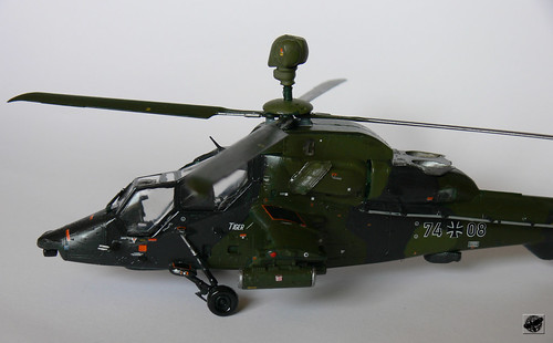
Those orange things are cameras for testing. And that 'condom' is some ground crew being lazy with his jacket. However, it goes without saying that I love our LCH much moreshiv wrote:Well I can see a hideous orange thing sitting right in front of the front cockpit blinding the chap there and humongous ugly tourist windows, no electro optical sensor and a radar that can only see front and sides and a stupid looking floppy used condom like thing hanging off the gun. I hope none of those is going to get incorporated. Wiki says the service ceiling is 4000 meters. Enough to go and crash into the side of a Himalayan mountainCraig Alpert wrote:http://media.defenseindustrydaily.com/i ... way_lg.jpg
Tiger HAD testing... Maybe future variants of LCH Could incorporate some of the features present uptop! Wishful thinking, but depending on how much weight is shredded in the current LCH, it is very doable!
LCH and other Helicopters Discussion Thread
Re: LCH and other Helicopters Discussion Thread
-
member_22539
- BRF Oldie
- Posts: 2022
- Joined: 11 Aug 2016 06:14
Re: LCH and other Helicopters Discussion Thread
shiv wrote: Well I can see a hideous orange thing sitting right in front of the front cockpit blinding the chap there and humongous ugly tourist windows, no electro optical sensor and a radar that can only see front and sides and a stupid looking floppy used condom like thing hanging off the gun. I hope none of those is going to get incorporated. Wiki says the service ceiling is 4000 meters. Enough to go and crash into the side of a Himalayan mountain
-
Craig Alpert
- BRFite
- Posts: 1438
- Joined: 09 Oct 2009 17:36
- Location: Behind Enemy Lines
Re: LCH and other Helicopters Discussion Thread
Unless I missed your sarcasm, You do realize that "hideous orange thing" is a Test equipment correctshiv wrote:
Well I can see a hideous orange thing sitting right in front of the front cockpit blinding the chap there
Again, Unless I missed your sarcasm, atleast Tiger has a Radar!shiv wrote:a radar that can only see front and sides
Re: LCH and other Helicopters Discussion Thread
Well you wished for a whole lot of Tiger things on the LCH. I was talking about what i did not want to see. There is a lot about the Tiger that i do not want to see on the LCH. I worry that you might be wishing for all the drawbacks including the worthless service ceiling.Craig Alpert wrote:Unless I missed your sarcasm, You do realize that "hideous orange thing" is a Test equipment correctshiv wrote:
Well I can see a hideous orange thing sitting right in front of the front cockpit blinding the chap thereIt doesn't come as part of a standardize package!
Again, Unless I missed your sarcasm, atleast Tiger has a Radar!shiv wrote:a radar that can only see front and sides
Did you really want a radar that is half blind because it is embedded in the body because they could not solve the mast vibration issues that the Apache designers have solved? How about no radar rather than half radar? But I admit the radar will detect the mountain before hitting it.
Sarcasm? Take it that way if you want. I could be serious.
Re: LCH and other Helicopters Discussion Thread
In any case, that isn't a radar, it's the optronic sighting system. It faces towards the rear in the 'rest' position.
Bliss to see
So no, tiger doesn't have a radar yet.
Bliss to see
So no, tiger doesn't have a radar yet.
Re: LCH and other Helicopters Discussion Thread
What is interesting is the position of the sensor..... definitely clarifies the doubt that the over the nose sensor in LCH causes no 'blind spot'
Re: LCH and other Helicopters Discussion Thread
Sorry saar, perhaps you missed it - why was the doubt any less clarified when Hari Nair said it? Do we have to get proof from Eurocopter?SidSom wrote:What is interesting is the position of the sensor..... definitely clarifies the doubt that the over the nose sensor in LCH causes no 'blind spot'
-
Bala Vignesh
- BRF Oldie
- Posts: 2149
- Joined: 30 Apr 2009 02:02
- Location: Standing at the edge of the cliff
- Contact:
Re: LCH and other Helicopters Discussion Thread
Shiv saar,
That line about the radar detecting the mountain before crashing had me rolling..
About the things that tiger has that i wish for LCH is the funding.. Nothing more..
That line about the radar detecting the mountain before crashing had me rolling..
About the things that tiger has that i wish for LCH is the funding.. Nothing more..
-
Bala Vignesh
- BRF Oldie
- Posts: 2149
- Joined: 30 Apr 2009 02:02
- Location: Standing at the edge of the cliff
- Contact:
Re: LCH and other Helicopters Discussion Thread
Hari Nair Sir,
Thanks for sharing such an awesome pic.. A round of whatever you have when, if ever, we meet..
Thanks for sharing such an awesome pic.. A round of whatever you have when, if ever, we meet..
-
Craig Alpert
- BRFite
- Posts: 1438
- Joined: 09 Oct 2009 17:36
- Location: Behind Enemy Lines
Re: LCH and other Helicopters Discussion Thread
Okay let's not start with selective reading first. I had said "some" not a "whole lot" big difference! The features that I was reffering to were passive weapons sys such as CM's & Radars & rotor blade noise suppressors.shiv wrote:Well you wished for a whole lot of Tiger things on the LCH.
Negative! I don't want those drawbacks on LCH. LCH is built around Indian Requirements and Operating ceiling in mind. I'm in content with you on this.shiv wrote: I was talking about what i did not want to see. There is a lot about the Tiger that i do not want to see on the LCH. I worry that you might be wishing for all the drawbacks including the worthless service ceiling.
My career in the service has taught me one thing, something is better than nothing! A radar with limitations is still better than flying with no radar depending on your mission profile!shiv wrote:Did you really want a radar that is half blind because it is embedded in the body because they could not solve the mast vibration issues that the Apache designers have solved? How about no radar rather than half radar? But I admit the radar will detect the mountain before hitting it. .
Re: LCH and other Helicopters Discussion Thread
as long as the helo is 100% stealth and passive scanning mode, burst moded radar is all that we need. I don't think we have super skirosky type stealths in our plans.
Re: LCH and other Helicopters Discussion Thread
Absolutely sir. A helo with limitations should similarly be better than no helo at all.Craig Alpert wrote: My career in the service has taught me one thing, something is better than nothing! A radar with limitations is still better than flying with no radar depending on your mission profile!
Both LCH and the Tiger have their limitations. What was it about the Tiger you wanted to see on the LCH? You did not specify.
I have a reason for doing this. To be very frank your post looked to me like a fanboy post of a genre which instantly compares anything Indian with something from abroad merely to point out what is better and desirable in the non Indian one. I did exactly the opposite like an Indian fanboy because someone has to play that role too.
Re: LCH and other Helicopters Discussion Thread
shiv wrote:Well I can see a hideous orange thing sitting right in front of the front cockpit blinding the chap there and humongous ugly tourist windows, no electro optical sensor and a radar that can only see front and sides and a stupid looking floppy used condom like thing hanging off the gun. I hope none of those is going to get incorporated. Wiki says the service ceiling is 4000 meters. Enough to go and crash into the side of a Himalayan mountainCraig Alpert wrote:http://media.defenseindustrydaily.com/i ... way_lg.jpg
Tiger HAD testing... Maybe future variants of LCH Could incorporate some of the features present uptop! Wishful thinking, but depending on how much weight is shredded in the current LCH, it is very doable!
Re: LCH and other Helicopters Discussion Thread
To rephrase.....Looking at the optical sensor near the rotor I got the doubt that this was a bad place for the sensor. Then remembered HNair sirs clarification that at alts and ranges it would be used at it would not make a diff if it was above the nose or in this case near the rotor.shiv wrote:Sorry saar, perhaps you missed it - why was the doubt any less clarified when Hari Nair said it? Do we have to get proof from Eurocopter?SidSom wrote:What is interesting is the position of the sensor..... definitely clarifies the doubt that the over the nose sensor in LCH causes no 'blind spot'
-
Craig Alpert
- BRFite
- Posts: 1438
- Joined: 09 Oct 2009 17:36
- Location: Behind Enemy Lines
Re: LCH and other Helicopters Discussion Thread
Correct, I did not specify that in my original post. Incase you missed it in the previous post, The features that I was referring to were passive weapons sys such as Counter Measures & Radars & rotor blade noise suppressors.shiv wrote: Both LCH and the Tiger have their limitations. What was it about the Tiger you wanted to see on the LCH? You did not specify.
shiv wrote: To be very frank your post looked to me like a fanboy post of a genre which instantly compares anything Indian with something from abroad merely to point out what is better and desirable in the non Indian one. I did exactly the opposite like an Indian fanboy because someone has to play that role too.
In terms of what is better, let's face it we all know where HAL stands as oppose to its counterparts however, "desirable in the non-Indian one" - Absolutely! Why not? What's wrong with wishful thinking? Haven't you ever wondered of exploiting a system to its full potential or perhaps potentials that you were unaware of that it can achieve? A little more R&D into this would only benefit HAL and give it fair chance to play a bigger part in the IAF & possibly earn it a seat at the big boy table. Just my 2 cents!
Rest assured, I’m not a fanboy of any systems - I've seen enough to know that technology leap plays a significant part in giving you an upper hand over your adversary; however I've seen firsthand that wars are won with strategies and equipments on hand.
Re: LCH and other Helicopters Discussion Thread
So your less than complimentary views of HAL are being painted on to the LCH. And because HAL stands in a particular place as compared to its counterparts (which you refuse to commit) the Tiger needs to be copied? I know you did not say this originally, but the posting of a huge photo of the Tiger with the cryptic message: "Tiger HAD testing... Maybe future variants of LCH Could incorporate some of the features present uptop! Wishful thinking, but depending on how much weight is shredded in the current LCH, it is very doable!" suggests that you were able to see some fantastic features in the Tiger that I was unable to see.Craig Alpert wrote: In terms of what is better, let's face it we all know where HAL stands as oppose to its counterparts however, "desirable in the non-Indian one" - Absolutely! Why not? What's wrong with wishful thinking?
And now you say that your feelings are related to your views on "where HAL stands"? I may have been spot on in my reading of the sense of your post.
However I am fully aware of where the LCH scores over the Tiger. You failed to specify what you saw as worthy of copying and you cannot expect everyone to be aware of what you have in your mind. I specified what it is about the Tiger that must not be copied. And for that you are giving me a lesson about HAL's pedigree and your deep personal insight into technology?Craig Alpert wrote:Haven't you ever wondered of exploiting a system to its full potential or perhaps potentials that you were unaware of that it can achieve?
Lets get this straight. I am an out and out LCH fanboy. I am not claiming that it's the best in the world, but neither am I going around passing dark hints about its less than pedigree antecedents at HAL and making suggestions of how "we all" know where HAL stands as opposed to its counterparts. Your views about pedigree and antecedents are confirmation about your attitude to me, which is something that I read instantly when I saw that Tiger post of yours. It is also a lesson that I will use in future to diss or praise something based on its perceived pedigree.Craig Alpert wrote:Rest assured, I’m not a fanboy of any systems - I've seen enough to know that technology leap plays a significant part in giving you an upper hand over your adversary; however I've seen firsthand that wars are won with strategies and equipments on hand.
Re: LCH and other Helicopters Discussion Thread
the pic of the tigre in previous page does indeed reveal the blade tip noise suppressor design developed by eurocopter. older pics of tigre dont show it. its like the end of the rotor instead of being sharp cut, is shaped like a boomerang with a trailing knife edge.
http://static.flickr.com/3041/2724840316_a4715779d1.jpg
the optronic ball in the nose sounds like a better position to me - less obstructed by the fuselage for engaging near targets. the apache longbow layout sounds like the best available. optronics in nose and radar atop the mast...abd big CFT type cheek fairings for avionics and fuel bays, plus a place for SF troopers to stand on in shack and awe kamandu pics
Re: LCH and other Helicopters Discussion Thread
There is now a fair amount of information about rotors and noise, but less info about rotor noise versus efficiency (fuel efficiency/lift/altitude capability etc) . Every link I find suggests that noise reduction features tend to reduce aerodynamic efficiency. Also there is very little information about whether noise reduction is achieved at all power settings, heights and speeds or whether there is a narrow band of speed/power/altitude where noise reduction is maximal.
Precious little information is available other than a large number of technical papers detailing causes of noise and noise modeling and prediction. In the meantine Eurocopterhas gone apeshit talking about its "Blue edge" rotor blade tips but there is not a chirp about fuel and lift efficiency gains or losses. One thing is sure. If there was a gain in efficiency, they would have announced it and tomtommed it from the highest minarets.
Slobbering after photos of helos with noise reduction rotor tips sounds more fanboyish to me than any serious technical commentary and this is something that probably requires a little attention and study on the forum.
Helicopter noise is a big deal in European and American cities. Dropping supplies or supporting troops or casevac at over 5000 meters is not an issue for either the Europeans or Americans unless they are looking to sell helos to India, China, Pakistan or Chile. And if it was, guess where the testing would have to be done?
-
member_22605
- BRFite
- Posts: 159
- Joined: 11 Aug 2016 06:14
Re: LCH and other Helicopters Discussion Thread
If you can observe carefully the tigre's rotor(the root section mainly) is very very very similar to the ALH/LCH rotor and it uses the same lead-lag damper that the ALH/LCH used previously. The tip is different though and am not sure how much of a difference that makes(maybe hari sir can elaborate if he finds it fit). I was even told of cases where eurocopter (erstwhile MBB) guys would seek our root end section test data(most crucial test for a rigid rotor) by one of our HOD's but not comment on the data AT ALL.(i have a story on the general indian sense of inferiority despite being almost world-class which i will try and post in the relevant thread )
Re: LCH and other Helicopters Discussion Thread
even the basic Dhruv is pretty quiet...a quiet humming vs the metallic clanking of the Mi17 enough to wake up anyone.
Re: LCH and other Helicopters Discussion Thread
Have we considered the BERP blade for the LCH?
http://terpconnect.umd.edu/~leishman/Aero/berp.html
ENAE 632 --The British Experimental Rotor Program (BERP) Blade
What is the BERP blade?
"The BERP blade was the result of ten-years (1976-1986) of aerodynamic research collaboration between Westland Helicopters and the Royal Aircraft Establishment.
This research paid off on 11th. August 1986 when the Westland company demonstrator Lynx (G-LYNX) attained the world absolute speed record for any helicopter, which remains in place more than ten years later. The Lynx achieved an average speed over a 15km course of 249.1 mph (400.87 kph), which broke the previous record of 228mph (367 kph). This high speed could not have been achieved without the use of the BERP blade.
The confidence that has since been established with the BERP blade means that this technology is now being applied to other helicopters. For example, the BERP blade will be standard equipment on the Lynx III battlefield helicopter and the new EH-101, the latter which is being developed jointly by Westland and Agusta. "
How does it work?
If we wish to reduce compressibility effects in forward flight, we can use sweep on the tip of a rotor blade. Many modern helicopters use some form of simple sweepback on the blade tip. Examples are the UH-60 Blackhawk and the AH-64 Apache.
However, so we don't get center of gravity or aerodynamic center movements aft of the blade elastic axis (which can introduce undesirable aerodynamic and inertial couplings), then the tip must be configured with an area shift forward. This can be kept to a minimum by recognizing that the Mach number is varying along the blade so we do not have to use a constant sweep angle, thereby minimizing the amount of forward area shift.
The methodology used in the design of the BERP blade ensures that the effective Mach number normal to the blade remains nominally constant over the swept region. The maximum sweep employed on the large part of the BERP blade is 30 degrees and the tip starts at a non-dimensional radius r/R=cos 30 = 86% radius. The area distribution of this tip region is configured to ensure that the mean tip center of pressure is located on the elastic axis of the blade. This is done by offsetting the location of the local 1/4-chord axis forward at 86% radius.
This offset also produces a diskontinuity in the leading edge (referred to as a notch), which results in other interesting effects. For example, recent calculations using a CFD code based on the Navier-Stokes equations, has shown that this "notch" actually helps to further reduce the strength of shock waves on the blade. Thus, an unexpected by-product of the notch over and above the basic effect of sweep is to help to reduce compressibility effects even further.
We must also recognize that a swept tip geometry of this sort will not necessarily improve the performance of the blade at high angles of attack corresponding to the retreating side of the disk. In fact, experience has shown that a swept tip blade can have an inferior stalling characteristic compared to the standard blade tip.
The BERP blade employs a final geometry that performs as a swept tip at high Mach numbers and low angles of attack, yet also enables the tip to operate at very high angles of attack without stalling. This latter attribute was obtained by radically increasing the sweep of the outermost part of the tip (the outer 2% approximately) to a value (70 degrees) where any significant angle of attack will cause leading edge flow separation.
Because the leading edge is so highly swept, this leading edge separation develops into a stable vortex structure which rolls around the leading edge and eventually sits over the upper surface (as on a delta wing aircraft). This mechanism is enhanced by making the leading edge of the airfoil in this region relatively sharp.
As the angle of attack is increased, then this vortex begins to develop from a point further and further forward along the leading edge, following the planform geometry into the more moderately swept region. At a sufficiently high angle of attack, the vortex will initiate close to the forward most part of the leading edge near the "notch" region.
Evidence has shown that a strong "notch" vortex is also formed, which is trailed streamwise across the blade. This vortex acts like an aerodynamic fence and retards the flow separation region from encroaching into the tip region. Further increases in angle of attack make little change to the flow structure until a very high angle of attack is reached (in the vicinity of 22 degrees!) when the flow will grossly separate. For a conventional tip planform, a similar gross flow breakdown would be expected to occur at about 12 degrees local angle of attack.
Therefore, the BERP blade manages to make the best of both worlds by reducing compressibility effects on the advancing blade and delaying the onset of retreating blade stall. The net result is a significant increase in the operational flight envelope.
Re: LCH and other Helicopters Discussion Thread
I think I saw the LCH flying back to it's nest just a while ago! Can anybody confirm?!
Re: LCH and other Helicopters Discussion Thread
Still no "burping"?
Re: LCH and other Helicopters Discussion Thread
Unusual pic there of the Tiger - appears to have been instrumented for weapons release tests- those cams & temperature sensors are perhaps there to record clearances & blast temperatures.Craig Alpert wrote:Tiger HAD testing... Maybe future variants of LCH Could incorporate some of the features present uptop! Wishful thinking, but depending on how much weight is shredded in the current LCH, it is very doable!
FC Radar on the Tiger? Have I missed something there? I understand that it has an EO (Day & Night) sensor - and a pretty good one at that.
Yes the Tiger does have some pretty good tricks up its sleeve - especially that Mauser cannon (without that stuff hanging at its end in that pic which Shiv so aptly referred to, of course!).
Craig- are you pointing towards anything specific on the Tiger or are you referring in general terms?
@Philip - Well the BERP is neither the pioneer nor the only rotor blade type with variable aerofoil sections along its span - almost all rotor blades have it to improve their efficiency - in fact have been having it for at least the past decade! You could check out for yourself at the next AeroIndia whilst having a dekko at all the helicopters there. The BERP of course appears to have had the best advertising. Not so sure about its high altitude capabilities during hover, though.
Re: LCH and other Helicopters Discussion Thread
You have to remember that the BERP blade was developed between 1976-1986. Back then it was pioneer, but now everyone would have adopted it.Hari Nair wrote:...
@Philip - Well the BERP is neither the pioneer nor the only rotor blade type with variable aerofoil sections along its span - almost all rotor blades have it to improve their efficiency - in fact have been having it for at least the past decade! You could check out for yourself at the next AeroIndia whilst having a dekko at all the helicopters there. The BERP of course appears to have had the best advertising. Not so sure about its high altitude capabilities during hover, though.
Re: LCH and other Helicopters Discussion Thread
globalsecurity updated their web on NOTAR copter used for geronimo ops.
http://www.globalsecurity.org/military/ ... t/mh-x.htm
http://www.globalsecurity.org/military/ ... t/mh-x.htm
Re: LCH and other Helicopters Discussion Thread
I think one thing is missed in all the articles I read about noise reduction and helicopter rotor blades. All of them refer to a degradation of performance. In this article the degradation is said to be minimal. If I take "minimal" as meaning that 90-95% of the previous performance is achieved by the new stealthy blades - this may well be great at sea level or say elevations up to 5000 feet or 8000 feetSaiK wrote:globalsecurity updated their web on NOTAR copter used for geronimo ops.
http://www.globalsecurity.org/military/ ... t/mh-x.htm
But when you need a helo that has to carry the maximum payload possible to heights of say 20,000 feet - a 5 to 10 % degradation will mean that it reaches only 18-19000 feet. The other point is that "minimum degradation" is not tested by any of these companies at 20,000 feet because they have nowhere to try and land and take off at such heights unless they take prototypes to Chile, India, Pakistan or China. India's helos are operating at the outer limits of what is physically possible given current technology. India's experience and data at those altitudes is cutting edge.
If you are looking to squeeze maximum performance out of a helicopter in mountains that go up over 22,000 feet, fancy noise reduction methods may all be performance degrading factors. Naturally, the people who advertise noise reduction are not going to advertise this latter possibility.
-
adityadange
- BRFite
- Posts: 274
- Joined: 04 Aug 2011 11:34
Re: LCH and other Helicopters Discussion Thread
i am not expert but one point worth noting with respect to noise at high altitudes is air density. we all know sound cannot travel in vaccume and its speed decreases as density of the medium through which sound is passing decreases. at 20k feet air density is very low. naturally less air is available to carry sound waves. and so the noise created by rotor blades will not reach farther and faster to enemy position. so better stealth wrt noise is achieved naturally.
Re: LCH and other Helicopters Discussion Thread
In any case having a helicopter that performs at those altitudes is itself an advantage. Rotor noise is only one of a number of components that lead to helo noise. There is an online video of a Paki F-7 crash at take off (initially uploaded on Liveleak as an Indian MiG 21 crash). Listen to the sound of the Alouette III helo in that video below and guess what you hear. The video starts at the time the helicopter can be heard and later seen flyingadityadange wrote:i am not expert but one point worth noting with respect to noise at high altitudes is air density. we all know sound cannot travel in vaccume and its speed decreases as density of the medium through which sound is passing decreases. at 20k feet air density is very low. naturally less air is available to carry sound waves. and so the noise created by rotor blades will not reach farther and faster to enemy position. so better stealth wrt noise is achieved naturally.
http://www.youtube.com/watch?feature=pl ... 79c#t=195s
Re: LCH and other Helicopters Discussion Thread
Saw the LCH TD1 on my way to office today. I'd previously spotted it from far a few days back (a few posts back) so today I was ready for a 'say cheese' and snap!
Re: LCH and other Helicopters Discussion Thread
Good work. You need quick reflexes to do that. Brilliant stuff.saje wrote:Saw the LCH TD1 on my way to office today. I'd previously spotted it from far a few days back (a few posts back) so today I was ready for a 'say cheese' and snap!
-
adityadange
- BRFite
- Posts: 274
- Joined: 04 Aug 2011 11:34
Re: LCH and other Helicopters Discussion Thread
if i am not wrong the main noise is of the engine. but i noticed it could be heard well only when the helicopter flies past to the camera i.e. from rear of the heli.shiv wrote: In any case having a helicopter that performs at those altitudes is itself an advantage. Rotor noise is only one of a number of components that lead to helo noise. There is an online video of a Paki F-7 crash at take off (initially uploaded on Liveleak as an Indian MiG 21 crash). Listen to the sound of the Alouette III helo in that video below and guess what you hear. The video starts at the time the helicopter can be heard and later seen flying
http://www.youtube.com/watch?feature=pl ... 79c#t=195s
Re: LCH and other Helicopters Discussion Thread
THere are hell of a lot of Armchair Internet warriors from India who have commented Flying coffin IAF without understanding that it is PAF F-7 crash. Shows how many are so well informed thanks to DDM and Aman Ki Asha, the whole lot of them fell for the Paki trick.
Re: LCH and other Helicopters Discussion Thread
Actually speed of sound in the atmosphere is directly proportional to the square root of air temperature (absolute temperature in Kelvin) - which means at high altitude, as the temperature decreases, so does the speed of sound. Density is not a factor here.adityadange wrote:i am not expert but one point worth noting with respect to noise at high altitudes is air density. we all know sound cannot travel in vaccume and its speed decreases as density of the medium through which sound is passing decreases. at 20k feet air density is very low. naturally less air is available to carry sound waves. and so the noise created by rotor blades will not reach farther and faster to enemy position. so better stealth wrt noise is achieved naturally.
How much distance would the noise travel ? - Well it depends on the ambient noise levels and the terrain also. In a valley at high altitude in the Himalayas, the noise of a helicopter would be funneled by the hills and given the usually low ambient noise level, an observer in the valley or mountainside will perhaps be able to hear the helicopter further away then in downtown New Delhi at the same distance. On the other hand, an observer in an adjacent valley may not be able to hear it at all, since the intervening mountain ridges may act as a shield.
Wrong there!srai wrote:You have to remember that the BERP blade was developed between 1976-1986. Back then it was pioneer, but now everyone would have adopted it.Hari Nair wrote:...
@Philip - Well the BERP is neither the pioneer nor the only rotor blade type with variable aerofoil sections along its span - almost all rotor blades have it to improve their efficiency - in fact have been having it for at least the past decade! You could check out for yourself at the next AeroIndia whilst having a dekko at all the helicopters there. The BERP of course appears to have had the best advertising. Not so sure about its high altitude capabilities during hover, though.
Other R&D agencies (ONERA in France, Sikorsky, Boeing in US, MBB in germany, etc) already had variable planforms going when the BERP was being developed. BERP's trade-mark paddle-tipped blades were meant to enhance speed - however, the original BERP planform was not optimised for hover performance. The paddle-tip is one approach to the problem of increasing forward speed- there are several other solutions that are also in vogue. The ALH's DMH-4 and DMH-3 variable planforms had also evolved roughly in the same era when the BERP evolved. I said it then and am saying it again - BERP's no way a pioneer in this field - they definitely have had the best advertising!
Re: LCH and other Helicopters Discussion Thread
Hari Nair saab, could you please update us on what's happening on the LCH development front?
Re: LCH and other Helicopters Discussion Thread
Saw one flying quite low near Agara today around 11 am
Re: LCH and other Helicopters Discussion Thread
Hari Nair Sahab/ Raghu,
I see that the armament boom has been turned into a aerofoil and been given a higher sweep to reduce drag. I think that it has been given a higher anhedral as well. Is it true? If yes, why?
I see the new fairings on the front landing gear. Nothing on the tail langing gear. However the landing gear seems to provide a much larger frontal area and that too flat. Yet it has not been covers. Is it in the works? Or is the gear is too wide to be covered i.e. any savings in drag is outweighed by the weight of the fairing? Or is it because the arm swings too much between landing and extended positions.
P.S. Needless to say, please divulge whatever you can/should.
Re: LCH and other Helicopters Discussion Thread
Light Combat Helicopter Sea-level Trials From Tomorrow - Livefist
India's Light Combat Helicopter (LCH) is all set to begin a week of sea-level trials early tomorrow morning at Tambaram, on the outskirts of Chennai. A prototype of the LCH landed at Tambaram today along with a chase helicopter. The trials will include speed calibration and manoeuverability trials. The trials which could stretch to ten days will include generic performance and handling at sea-level (Bangalore is at 3,000 feet above sea level), calibration of the LCH's air speed measurement system and measurement of forces in terms of stress on various components of the platform.
Livefist wishes the test team the very best for the week ahead!
Incidentally -- something big to look out for soon is the third prototype of the LCH, which my sources tell me will be the defining shape and configuration of the final LCH. I'm told it will look significantly different in terms of dimensions too.
Re: LCH and other Helicopters Discussion Thread
Hari Nair saab, any chance that you could tell us what to expect from the third LCH prototype?


