How feasible would it be (schedule wise) to fit a different engine of similar capabilities into the Mk1, if US is not ready?NRao wrote:Is that supposed to mean that the US in on board with selling the LCA with the GE engine?
LCA News and Discussions, 22-Oct-2013
-
member_28722
- BRFite
- Posts: 333
- Joined: 11 Aug 2016 06:14
Re: LCA News and Discussions, 22-Oct-2013
Last edited by Indranil on 29 Jan 2015 05:52, edited 1 time in total.
Reason: This is a utterly silly question. Do a Google search, or a search in this thread. If you still cannot find the answer, ask in the Newbie thread. You are excused for your first mistake. Warnings will follow from the second.
Reason: This is a utterly silly question. Do a Google search, or a search in this thread. If you still cannot find the answer, ask in the Newbie thread. You are excused for your first mistake. Warnings will follow from the second.
Re: LCA News and Discussions, 22-Oct-2013
Does "similar capability" mean power, or weight, or size to fit exactly into a slot in the LCA designed for the GE engine. If you can name one engine that has exactly the same size, and similar power and weight I will tell you about the feasibility.saurabh.mhapsekar wrote:How feasible would it be (schedule wise) to fit a different engine of similar capabilities into the Mk1, if US is not ready?NRao wrote:Is that supposed to mean that the US in on board with selling the LCA with the GE engine?
Re: LCA News and Discussions, 22-Oct-2013
I am going to open a can of worms here. Once again, answer only if you can give technical details. Replies with wrong technical details will be roasted and poster will be warned.
Hypothesis 1: LCA does not have an APU
Reasons: Otherwise LCA would not have required a hydrazine powered EPU (emergency power unit) for high AoA testing: Approach to High Angle of Attack Testing of Light Combat Aircraft LCA Tejas.
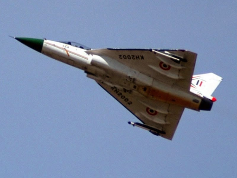
Return to an old question: What is the dorsal air intake scoop at the tail fin for?
Case 1: This air is used along with the engine bleed air to cool the afterburner duct. This may be true because this air combines with the bleed air from the engine, then travels through the AB duct and leaves through the gap that I have pointed to before. This will also aid in IR signature suppression. The problem with this theory is that Tejas TDs did not have this scoop, but had two other scoops on each side of the dorsal spine. These scoops have been retained even now and are called "engine bay venting scoops". If air intake through these scoops was not sufficient, they could simply enlarged them. Why add a third bigger one, unless it provides more uniform cooling?
Case 2: The Environment Control System (ECS) in Tejas also used the bleed air from the engine by cooling it through a series of heat exchangers and a Cold Air Unit. The air from the dorsal air intake is used to provide fresh air to this mixture.
Case 3: Both of the above. The air from the 3 scoops mixes with the bleed air of the engine. The ECS sucks in the air it needs and rest is passes through the AB duct.
Does anybody know for sure? If not, can somebody ask at AI-15.
Raman sahab, where did you learn about the new Ram intake being controllable? All the above may be bogus, but if either case 1 or 3 is right, there is no question of spillage drag. Actually initially LSP-7 did not have this scoop. It just had a slit in the bump. They must have found out this is not providing enough air and changed back to this scoop as a quick fix till they find a permanent solution. May be unrelated, but I did see a tender to CAD studies to design an optimum intake at fin root for cooling avionics. Let me dig it out.
Hypothesis 1: LCA does not have an APU
Reasons: Otherwise LCA would not have required a hydrazine powered EPU (emergency power unit) for high AoA testing: Approach to High Angle of Attack Testing of Light Combat Aircraft LCA Tejas.
Return to an old question: What is the dorsal air intake scoop at the tail fin for?
Case 1: This air is used along with the engine bleed air to cool the afterburner duct. This may be true because this air combines with the bleed air from the engine, then travels through the AB duct and leaves through the gap that I have pointed to before. This will also aid in IR signature suppression. The problem with this theory is that Tejas TDs did not have this scoop, but had two other scoops on each side of the dorsal spine. These scoops have been retained even now and are called "engine bay venting scoops". If air intake through these scoops was not sufficient, they could simply enlarged them. Why add a third bigger one, unless it provides more uniform cooling?
Case 2: The Environment Control System (ECS) in Tejas also used the bleed air from the engine by cooling it through a series of heat exchangers and a Cold Air Unit. The air from the dorsal air intake is used to provide fresh air to this mixture.
Case 3: Both of the above. The air from the 3 scoops mixes with the bleed air of the engine. The ECS sucks in the air it needs and rest is passes through the AB duct.
Does anybody know for sure? If not, can somebody ask at AI-15.
Raman sahab, where did you learn about the new Ram intake being controllable? All the above may be bogus, but if either case 1 or 3 is right, there is no question of spillage drag. Actually initially LSP-7 did not have this scoop. It just had a slit in the bump. They must have found out this is not providing enough air and changed back to this scoop as a quick fix till they find a permanent solution. May be unrelated, but I did see a tender to CAD studies to design an optimum intake at fin root for cooling avionics. Let me dig it out.
Re: LCA News and Discussions, 22-Oct-2013
Saurabh , Short answer: Very difficult as the plane is designed around the engine.
Would require total redesign. Besides LCA is unstable design which means the exact characteristics of the engine and plane are matched.
Reason is the engine is not podded like a transport/passenger plane where you can swap the engines.
Even there L1011 plane in the 1970s was hugely behind schedule when RR did not deliver the engine. LM exited the passenger plane business!
Re: LCA News and Discussions, 22-Oct-2013
Recently we were looking for GE or EJ-200 engines for LCA. Of course we know that F-414 was selected, but does it mean that the two engines are similar enough to be aligned into the LCA airframe? Or have their been significant design changes in LCA to accommodate F-414?
I am quite a newbie to these technical matters since I have no expertise or experience in aerospace engineering.
I am quite a newbie to these technical matters since I have no expertise or experience in aerospace engineering.
Re: LCA News and Discussions, 22-Oct-2013
^^^ Please take it to the newbie thread.
Re: LCA News and Discussions, 22-Oct-2013
Tarmak posted on twitter a few days back that NP2 did hstt. May fly soon i suppose.
-
Shreeman
- BRF Oldie
- Posts: 3762
- Joined: 17 Jan 2007 15:31
- Location: bositiveneuj.blogspot.com
- Contact:
Re: LCA News and Discussions, 22-Oct-2013
Let me take a stab. The hypothesis is likely true. The primary evidence in support though should come from indigenization of JFS, secondary from the EPU and the like.indranilroy wrote:I am going to open a can of worms here. Once again, answer only if you can give technical details. Replies with wrong technical details will be roasted and poster will be warned.
Hypothesis 1: LCA does not have an APU
Reasons: Otherwise LCA would not have required a hydrazine powered EPU (emergency power unit) for high AoA testing: Approach to High Angle of Attack Testing of Light Combat Aircraft LCA Tejas.
Return to an old question: What is the dorsal air intake scoop at the tail fin for?
Case 1: This air is used along with the engine bleed air to cool the afterburner duct. This may be true because this air combines with the bleed air from the engine, then travels through the AB duct and leaves through the gap that I have pointed to before. This will also aid in IR signature suppression. The problem with this theory is that Tejas TDs did not have this scoop, but had two other scoops on each side of the dorsal spine. These scoops have been retained even now and are called "engine bay venting scoops". If air intake through these scoops was not sufficient, they could simply enlarged them. Why add a third bigger one, unless it provides more uniform cooling?
Case 2: The Environment Control System (ECS) in Tejas also used the bleed air from the engine by cooling it through a series of heat exchangers and a Cold Air Unit. The air from the dorsal air intake is used to provide fresh air to this mixture.
Case 3: Both of the above. The air from the 3 scoops mixes with the bleed air of the engine. The ECS sucks in the air it needs and rest is passes through the AB duct.
Does anybody know for sure? If not, can somebody ask at AI-15.
Raman sahab, where did you learn about the new Ram intake being controllable? All the above may be bogus, but if either case 1 or 3 is right, there is no question of spillage drag. Actually initially LSP-7 did not have this scoop. It just had a slit in the bump. They must have found out this is not providing enough air and changed back to this scoop as a quick fix till they find a permanent solution. May be unrelated, but I did see a tender to CAD studies to design an optimum intake at fin root for cooling avionics. Let me dig it out.
There are countless uses for the tail scoop, but environment management within the craft is the likely reason.
IR suppression is likely not the reason. Given that it has stuck around and been remodeled, I suspect things get hot under certain circumstances only, which may explain the need for a closing mechanism.
Again, since this sort of thing would only show up in actual testing, rapid cooling any other way might have been found to be unsuitable or needlessly complex. This also seems to dovetail with the missing skirt sections. Actual environmental readings may have been off compared to designed/predicted for certain areas.
I conjecture it has to do with engine environment management only. And that it might or might not stick around in 414 based Mk2. Who will ask at AI15?
Re: LCA News and Discussions, 22-Oct-2013
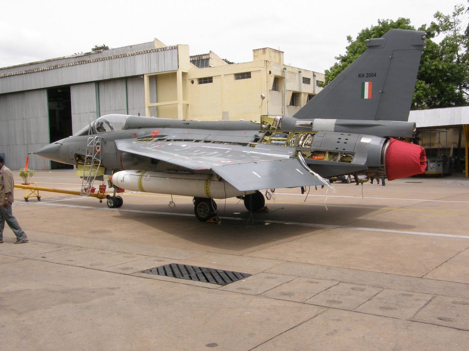
Indranil, The APU exhaust is visible on the right hand side of the aircraft, just below tail fin. The EPU is necessary to power electronics in case of catastrophic failure where even the fuel supply of even APU is cut off. F-16 also has a hydrazine powered EPU. APUs run for a prolonged period and EPUs only for a few minutes.
The engine bay cooling vents are also present.

The engine bay cooling vents are also present.
Re: LCA News and Discussions, 22-Oct-2013
indranilroy, I am not privy to any special information. It is just a guess.
I believe that Tejas has an APU, but it is possible that it is only a JFS and not a full blown APU. Conventionally, the APU is usually needed during start-up to provide electrical power for avionics, environmental control and to run the engine starter. Once the engine is on, the systems are run using the engine's power and the APU is switched off.
Note that presence of EPU does not mean that an APU is not present. During emergency, power is required almost immediately. In a single engined airplane there is not enough time to start up the APU, which, after all, is a small jet engine that needs a start-up sequence, time to stabilize, etc. since it is not always running.
As for the scoop, I guess I'm mistaken. I saw the new scoop and thought that it was in an open position vs the closed position on other aircraft and did not realize that it was the new configuration.
Re: LCA News and Discussions, 22-Oct-2013
@Thakur sahab,
You are right about:
1. EPU runs for a few minutes from engine flame-out to engine relight.
2. Cooling vents in your diagram. I called them "engine bay venting scoops".
3. F-16 houses a hydrazine powered EPU, as do many other modern fighters.
You are wrong about:
1. EPU is for running the avionics. It is for running the hydraulic pumps. From the paper:
@Raman sahab: The JFS can start or relight the engine up to a 6 km altitude. But it itself is started electrically using the onboard battery. The rectangular air intake of the JFS can be seen just aft of the MLG doors. The too NACA inlets aft of them (I guess) is again for cooling the engine bay.The hydraulic system is critical to recovery from spin as it powers the controls and ironically will be the first system that will be lost in case of engine flameout. The Emergency pump can supply flow for three min but not at the rate desired for full control activity. Thus it is necessary to provide a backup hydraulic power source, preferably for both main and emergency systems, of approx 60 lpm. The critical period for consideration whilst sizing the back up Emergency power Unit (EPU) pump will be from recovery to relight,when the chute would have been released and the ac flown in frozen gains until relight and recovery of on board hydraulics. While an APU could be used, it would probably not be able operate at the test altitudes. Currently the international standard is to use a hydrazine driven pump. However handling of this fluid has its own safety requirements and the EPU would have to be replenished at the taxy holding point prior to take off and a EPU contents indication should be available at telemetry. The triggering of this pump is also of importance as too early (switching it on before the test point) would deplete EPU fuel unnecessarily, and switching it on too late could lead to damage of the ac hydraulic system and delayed recovery. Linking the EPU to engine RPM or reducing actuator rates with RPM could be one of the options.
Re: LCA News and Discussions, 22-Oct-2013
Thakur_B, it could be the Jet Fuel Starter. Just wondering what other functions an APU would be needed for for a light aircraft when it could easily be hooked up to a ground unit. For larger aircraft you may need one.
Anyway, I'm not really qualified to comment too much on this.
Anyway, I'm not really qualified to comment too much on this.
Re: LCA News and Discussions, 22-Oct-2013
That one is probably the exhaust and, the grilled inlet between the MLG doors is probably the inlet, if this F-15 schematic is anything to go by.

Re: LCA News and Discussions, 22-Oct-2013
I think you are right. Explains why the rectangular opening is sooted.
Re: LCA News and Discussions, 22-Oct-2013
FYI
http://img7.imageshack.us/img7/4035/escaneo001.jpg
I wish we have a new updated one.
this is a nice view
http://i.imgur.com/V4bIFw6.jpg
http://img7.imageshack.us/img7/4035/escaneo001.jpg
I wish we have a new updated one.
this is a nice view
http://i.imgur.com/V4bIFw6.jpg
Last edited by Indranil on 30 Jan 2015 03:39, edited 1 time in total.
Reason: Does not add anything new. Let's keep the discussion as focussed as possible.
Reason: Does not add anything new. Let's keep the discussion as focussed as possible.
Re: LCA News and Discussions, 22-Oct-2013
Mixes up fibreglass as composite (subset as vs complete) but some interesting data
http://www.business-standard.com/articl ... 924_1.html
“The fibreglass (composite) content in the defence industry will alone be Rs 20,000 crore from the total Rs 200,000 crore worth spending in the development of indigenous defence systems in the next 10 years,” said Avinash Chander, chief of Defence Research and Development Organisation (DRDO), today.
In his inaugural address at the international conference on reinforced plastics here, Chander said the DRDO was working on raising the utilisation of fibreglass material components in the next version of light combat aircraft (LCA) Tejas equipped with Mark-II engine, from the “present 65 per cent to up to 80 per cent”.
“The wings for the aircraft are now totally being made out of fibreglass structures. We are going to look at having the entire fuselage made out of them. Once we achieve this, we want the domestic industry to manufacture the secondary (internal) structures in the aircraft,” he said.
......
Noting the use of fibreglass has been an integral part of the country's Agni series of missiles, he said research was happening to make use of them in the manufacture of submarines, unmanned aerial vehicles and light-weight radars.
Re: LCA News and Discussions, 22-Oct-2013
http://www.spsmai.com/exclusive/?id=192 ... Tejas-Mk.2
Aero India spotlight on LCA Tejas Mk.2
By SP's Special Correspondent
Photo Credit: SP's Special Correspondent
January 28, 2015: With the first production series LCA Tejas Mk.1 handed over to the IAF, and with more in the pipeline this year for squadron service first in Bengaluru and then Sulur in Tamil Nadu, this year's Aero India will fix the spotlight on the LCA Mk.2. With final operational clearance on the LCA Mk.1 for the Indian Air Force slated for the end of this year, and with the LCA Navy Mk.1 beginning its carrier compatbility trials successfully, [bb]the two Mk.1 programmes are effectively making progress in their final stages of development, clearing space now for attention to the LCA Mk.2, the platform that both the IAF and Indian Navy are looking forward to very keenly. [/b]The proposed platform, powered by the more powerful GE F414 turbofan (a deal that's finalised but yet to be signed), will be the true replacement of the MiG-21. It will be a more capable aircraft in every way, as first revealed at Aero India 2011. This year at the show in Bengaluru, there will be wide interest in the proposed platform. The Indian Air Force, sources say, has been putting custom pressure on the programme team to commit to better capabilities and timelines, and will be looking to see certain specifics announced or pledged at Aero India. Defence Minister Manohar Parrikar, who visited ADA earlier this month, is said to have expressed the need for far greater indigenous content on the LCA, maintaining that the current 60% level would be unacceptable on the LCA Mk.2. He was assured that project management and development sub-systems meant that the indigenous content percentage on the Mk.2 would be significantly higher from the start.
http://www.spsmai.com/exclusive/?id=195 ... oject-plan
HAL draws up priority project plan
By SP's Special Correspondent
Photo Credit: SP's Special Correspondent
January 28, 2015: As part of its effort to gear up for a higher-tempo role in defence production, a total of 111 technology projects have been identified by HAL in the areas of design, manufacture, avionics and material to support indigenisation and Prime Minister Narendra Modi's 'Make in India' campaign. The company has drawn up a modernisation and expansion plan for each division and R&D centre of the company to be implemented by 2018. These include the indigenous design & development of a mini UAV (8 kg class) for surveillance and reconnaissance, be part of a special purpose vehicle to design, develop and manufacture a Regional Civil Aircraft in collaboration with National Aeronautical Laboratory (NAL), move forward with the design and development of a 20 KN engine that was launched in 2012-13, to explore the acquisition of new and critical technologies through collaboration, co-development, transfer of technology agreements, formation of joint ventures etc. HAL has chalked out certain crucial projects such as Light Utility Helicopter (LUH), Light Combat Helicopter (LCH), HTT-40, Su-30 MKI, Light Combat Aircraft (LCA), Advanced Light Helicopter (ALH), Medium Multi Role Combat Aircraft (MMRCA) and a few others as its growth pillars moving forward, in addition to new projects. HAL believes that LCA, IJT and HTT-40 need to be its in-house technology drivers to demonstrate that the company is capable of delivering beyond license production of equipment, and helping. One of the major thrust areas for HAL this year onward will be exploiting the export potential of its products. The company will be hiring consultants this year to develop an appropriate marketing strategy for its defence and civil platforms.
Re: LCA News and Discussions, 22-Oct-2013
who is more established to develop engines? GTRE or HAL? should not GTRE be focused on developing various types of engines for HAL?
Last edited by Indranil on 30 Jan 2015 06:21, edited 1 time in total.
Reason: User warned for posting questions and/or data that have been discussed many times, despite repeated cautions.
Reason: User warned for posting questions and/or data that have been discussed many times, despite repeated cautions.
-
Shreeman
- BRF Oldie
- Posts: 3762
- Joined: 17 Jan 2007 15:31
- Location: bositiveneuj.blogspot.com
- Contact:
Re: LCA News and Discussions, 22-Oct-2013
Indranil,indranilroy wrote:I think you are right. Explains why the rectangular opening is sooted.
Actially the image does add something. It correlates the location of the jfs inlet/exhaust with its mounting location. A second APU or any other auxiliary that was never designed in the tail root is more than worthy of an AI15 inquiry. Something unusual must have happened if power to electronics is required in the air minus the engine and another power source was integrated.
I still say the tail root scoop doesnt appear to have anything with power generation given the recent JFS starts in Leh (reported just yesterday).
Re: LCA News and Discussions, 22-Oct-2013
IR IMO the dorsal scoop is for jfs. Tejas has 110 kW jfs unit meant to start the engine only. The free power turbine is connected to AMAGB which then powers the HP spool for starting the engine. I don't think that there is enough space for jfs aft of MLG bay and beneath the engine. Moreover the only major physical changes that we have seen in Tejas is the addition of the hump and scoop which points towards jfs integration. JMT.
-
Shreeman
- BRF Oldie
- Posts: 3762
- Joined: 17 Jan 2007 15:31
- Location: bositiveneuj.blogspot.com
- Contact:
Re: LCA News and Discussions, 22-Oct-2013
^^^
http://img7.imageshack.us/img7/4035/escaneo001.jpg
this shows the jfs location. the previous posts point to different inlet/exhausts for jfs.
http://img7.imageshack.us/img7/4035/escaneo001.jpg
this shows the jfs location. the previous posts point to different inlet/exhausts for jfs.
Re: LCA News and Discussions, 22-Oct-2013
JFS intakes and exhaust vents generally stay flush with the body because they are used mostly when the plane is stationary. If one uses scoops, then when the JFS is not working (which is almost always in flight), no air goes into the intake and everything is spilt out. Imagine the spillage drag. It is like flying with a cardboard stuck to the inlet of the scoop.Shreeman wrote:^^^
http://img7.imageshack.us/img7/4035/escaneo001.jpg
this shows the jfs location. the previous posts point to different inlet/exhausts for jfs.
AFAIK, the JFS is placed just aft of the MLG. The idea that the rectangular hole is an exhaust is also verified by this picture.
Having said that:
1. I do not know since when the JFS became part of the line-up. That will be great information.
2. I have no theory on what purpose is served by the metallic exhausts on both sides of the spine below the fin. Them being metallic suggest that the exhaust is hot.
That diagram is not current. It shows the state of the TDs.Shreeman wrote:^^^
http://img7.imageshack.us/img7/4035/escaneo001.jpg
this shows the jfs location. the previous posts point to different inlet/exhausts for jfs.
Re: LCA News and Discussions, 22-Oct-2013
Thanks. Makes sense, since accessory gearbox in GE 404 is mounted at the bottom, so the JFS is colocated with that.
Re: LCA News and Discussions, 22-Oct-2013
It just clicked me that AM Rajkumar in his book 'The Tejas story' mentioned that after the initial smoke issues with JFS, he instructed the team to make it euro 3/4 compliant. He was associated with Tejas from 1993 to 2001. So it means that JSF was there from the very begining i.e. first flight.indranilroy wrote: Having said that:
1. I do not know since when the JFS became part of the line-up. That will be great information.
Cheers....
-
Shreeman
- BRF Oldie
- Posts: 3762
- Joined: 17 Jan 2007 15:31
- Location: bositiveneuj.blogspot.com
- Contact:
Re: LCA News and Discussions, 22-Oct-2013
Check 1/27-1/28reports on JFS restarts in Leh. Its in there.
Re: LCA News and Discussions, 22-Oct-2013
Those two ducts have been at those locations since TD1.indranilroy wrote:Having said that:
1. I do not know since when the JFS became part of the line-up. That will be great information.
It is possible that JFS has been included since the beginning(?)
Those are afterburner venting ducts, as per the cutaway.2. I have no theory on what purpose is served by the metallic exhausts on both sides of the spine below the fin. Them being metallic suggest that the exhaust is hot.
Re: LCA News and Discussions, 22-Oct-2013
I am speaking of the vents marked as APU exhaust in this pic.
Re: LCA News and Discussions, 22-Oct-2013
Indranil,
Jet Fuel Starter was there from day 1, only it was earlier called Gas Turbine Starter Unit.
Check page 13 here http://tejas.gov.in/IOC-Brochure.pdf
Never heard of APU on Tejas.
Added later - More details here http://www.hal-india.com/Aero%20Engine/M__146
Jet Fuel Starter was there from day 1, only it was earlier called Gas Turbine Starter Unit.
Check page 13 here http://tejas.gov.in/IOC-Brochure.pdf
Never heard of APU on Tejas.
Added later - More details here http://www.hal-india.com/Aero%20Engine/M__146
Last edited by tsarkar on 30 Jan 2015 10:56, edited 1 time in total.
Re: LCA News and Discussions, 22-Oct-2013
That's what I am saying. There is no APU. So what is that dorsal scoop for?
Re: LCA News and Discussions, 22-Oct-2013
Is that a dorsal scoop a la F-16 Vista modification to bring in additional maneuvarability? The Americans had to scramble to get their fighters as nimble as the mig-29 and the sukhois and needed a series of modifications (physical and fly by wire) to be able to execute such maneuvers as the Pugachev.
Last edited by Indranil on 30 Jan 2015 11:56, edited 1 time in total.
Reason: This thread is on a tight lease. As I said earlier, if you speculate too wildly without knowledge, you will earn a warning. Well, now you have. If you wan't to speculate, take it to the newbie thread.
Reason: This thread is on a tight lease. As I said earlier, if you speculate too wildly without knowledge, you will earn a warning. Well, now you have. If you wan't to speculate, take it to the newbie thread.
Re: LCA News and Discussions, 22-Oct-2013
My understanding was it was for engine bay cooling. That part of the fuselage was composite that didn't dissipate heat like a metal fuselage would.
http://en.wikipedia.org/wiki/File:LCA_Composites.jpg
So the scoop was added. TD don't have the scoop. I speculate part of the skirting was removed to allow the cooling air to exit.
Disclaimer - Jotting down whatever I could remember from someone associated with the program.
http://en.wikipedia.org/wiki/File:LCA_Composites.jpg
So the scoop was added. TD don't have the scoop. I speculate part of the skirting was removed to allow the cooling air to exit.
Disclaimer - Jotting down whatever I could remember from someone associated with the program.
Re: LCA News and Discussions, 22-Oct-2013
I don't think Tejas needs an APU when it has JSF. They can very well make the JFS run the generator via AMAGB and a clutch mechanism. Engine bay cooling could be one reason but isn't it protected by a firewall anyway? Check this image posted by Indranil, it shows the innards of that hump. Looks like it's there to cool some electronics. Possibly EW related stuff.
http://3.bp.blogspot.com/_zUe7sq7m3h0/S ... +tank1.JPG
http://3.bp.blogspot.com/_zUe7sq7m3h0/S ... +tank1.JPG
Re: LCA News and Discussions, 22-Oct-2013
Yeah, I am increasingly getting sanguine that there is no APU on Tejas. When the engine flames-off, there is enough juice in the hydraulic pumps to go for about a minute. During this time EPU is comes up (either on pilot input or through the FCS sensing the fall in the engine RPM) and supports the hydrulic pumps for a few more minutes. During this time the JFS attempts to relight the engine.
The scoop is there to provide cool fresh air for one of the 3 cases I had speculated on the last page.
The scoop is there to provide cool fresh air for one of the 3 cases I had speculated on the last page.
Case 1: This air is used along with the engine bleed air to cool the afterburner duct. This may be true because this air combines with the bleed air from the engine, then travels through the AB duct and leaves through the gap (in skirting at the base of engine nozzle along the upper semicircle) that I have pointed to before. This will also aid in IR signature suppression. The problem with this theory is that Tejas TDs did not have this scoop, but had two other scoops on each side of the dorsal spine. These scoops have been retained even now and are called "engine bay venting scoops". If air intake through these scoops was not sufficient, then they could have simply enlarged them. Why add a third bigger one, unless it provides more uniform cooling?
Case 2: The Environment Control System (ECS) in Tejas also uses the bleed air from the engine by cooling it through a series of heat exchangers and a Cold Air Unit. The air from the dorsal air intake is used to provide fresh air to this mixture.
Case 3: Both of the above. The air from the 3 scoops mixes with the bleed air of the engine. The ECS sucks in the air it needs and rest is passed through the AB duct.
-
member_28932
- BRFite
- Posts: 107
- Joined: 11 Aug 2016 06:14
Re: LCA News and Discussions, 22-Oct-2013
This remind me a quotation of a Russian technologist who had said that If we are awarded the MMRCA contract, we shall transfer a technology to make plane highly maneuverable to India. I do not know what he was talking about but we should look into that. If we can improve the performance of our plane with consultancy such as this Russian technology or some come consultency in engine integration and air intake redesign, we should not mind in hiring these consultency. The contract should be performance based. i.e payment shall be in proportion to performance improvement.Yogi_G wrote:Is that a dorsal scoop a la F-16 Vista modification to bring in additional maneuvarability? The Americans had to scramble to get their fighters as nimble as the mig-29 and the sukhois and needed a series of modifications (physical and fly by wire) to be able to execute such maneuvers as the Pugachev.
Last edited by Indranil on 30 Jan 2015 20:23, edited 1 time in total.
Reason: This thread is on a tight lease. As I said earlier, if you speculate too wildly without knowledge, you will earn a warning. Well, now you have. If you wan't to speculate, take it to the newbie thread.
Reason: This thread is on a tight lease. As I said earlier, if you speculate too wildly without knowledge, you will earn a warning. Well, now you have. If you wan't to speculate, take it to the newbie thread.
Re: LCA News and Discussions, 22-Oct-2013
Similar openings can be seen at the port side behind cockpit on Tejas. Which is why I believe the intake at tail fin is for APU and not for jet fuel starter.Raman wrote:That one is probably the exhaust and, the grilled inlet between the MLG doors is probably the inlet, if this F-15 schematic is anything to go by.

A cooling air outlet would not require be required to be made out of metal. A hot APU or EPU exhaust might warrant that.indranilroy wrote: The scoop is there to provide cool fresh air for one of the 3 cases I had speculated on the last page.
Case 1: This air is used along with the engine bleed air to cool the afterburner duct. This may be true because this air combines with the bleed air from the engine, then travels through the AB duct and leaves through the gap (in skirting at the base of engine nozzle along the upper semicircle) that I have pointed to before. This will also aid in IR signature suppression. The problem with this theory is that Tejas TDs did not have this scoop, but had two other scoops on each side of the dorsal spine. These scoops have been retained even now and are called "engine bay venting scoops". If air intake through these scoops was not sufficient, then they could have simply enlarged them. Why add a third bigger one, unless it provides more uniform cooling?
Case 2: The Environment Control System (ECS) in Tejas also uses the bleed air from the engine by cooling it through a series of heat exchangers and a Cold Air Unit. The air from the dorsal air intake is used to provide fresh air to this mixture.
Case 3: Both of the above. The air from the 3 scoops mixes with the bleed air of the engine. The ECS sucks in the air it needs and rest is passed through the AB duct.
Re: LCA News and Discussions, 22-Oct-2013
This is a little silly post by you. Why would the JFS be behind the cockpit?Thakur_B wrote: Similar openings can be seen at the port side behind cockpit on Tejas. Which is why I believe the intake at tail fin is for APU and not for jet fuel starter.
Those openings are actually present on both sides, not just the port side. They are heat exchangers for the ECS. As I have said earlier, the ECS uses the bleed air from the 7th stage of the engine. One can see the pipe emanating from the side of the engine, travelling through the spine to the ECS equipment bay which is housed just behind the cockpit. There this air (at about 600 C) passes through 6 heat exchangers and a air cooling unit to bring down the temperature and pressure. The cooled air is then used for cockpit pressurization, deicing, cooling of avionics, demistifying the canopy etc. etc.

Re: LCA News and Discussions, 22-Oct-2013
On page 14 of Tejas: IOC Brochure:
This blog describes the experiences as head of R&D of a public sector undertaking(Bharat Heavy Plate & vessels Ltd).
Details of heat exchangers brazed
Dr.G.J.Guru RajaHeat Exchangers
Successfully designed, developed by BHEL-HPVP (Formerly BHPV) and flight qualified 10 types of compact plate-fin heat exchangers for LCA-TEJAS aircraft.
This blog describes the experiences as head of R&D of a public sector undertaking(Bharat Heavy Plate & vessels Ltd).
Details of heat exchangers brazed
vacuum brazed aluminium heat exhangers for aero space applications17 numbers of heat exchangers were to be brazed, some of aluminium and some of stainless steel.
The minimum core weight of the aluminium heat exchanger(Liquid-Air HE) was o.28 Kg and the finished weight of the same heat exchanger was 0.85 Kg. The maximum core weight of the aluminium heat exchanger(Secondary HE) was 8.78 Kg the finished weight was 12.0 Kg. The aluminium fins are as thin as 0,0762 mm.
There were a number of stainless steel heat exchangers. The minimum core weight of the heat exchanger(Precooler) was 8.8 Kg and the finished weight was 12.0 Kg. The maximum core weight(Primary HE} was 15.6 Kg and the maximum finished weight was 23.0 Kg. The fin thickness was 0.0762 mm.
If you look at the thickness of the fins the difficulty in brazing can be gauged. CLOSE CONTROL OF THE BRAZING TEMPERATURE WAS ESSENTIAL FOR THE SUCCESS OF THE BRAZING OF THESE HEAT EXCHANGERS.
All these heat exchangers are performing successfully in the Supersonic air craft developed by Aeronautical Development Agency ,LCA TEJAS, and have clocked hundreds of flight hours. India is one of the few countries which have such a sophisticated technology.
My association with this project was in the initial brazing trials as I left BHPV in 1995. Credit should go to R&D team led by Mr. Panigrahi DGM(R&D) who completed the project. Recently ADA has placed an order worth Rs.20 crores for a few sets of these heat exchangers.
Aeronautical Development Agency gave R&D of BHPV a development contract for the design of compact heat exchangers for the supersonic air craft which they were designing.The heat exchangers were to be fitted in an envelope volume specified by ADA. The smallest aluminium heat exchanger had dimensions of 130mm x 30mm x 55mm and the largest heat exchanger had dimensions of 250mm x 140mm x 370mm.
The smallest stainless steel heat exchanger had dimensions of 175mm x 118mm x 200mm and the largest heat exchanger had dimensions of 250mm x 140m x 282 mm.
The challenge was to optimise the design with in the space provided so that the heat exchangers meet the heat dissipating requirements. Our design engineers developed computer programmes to optimise the heat exchangers. It took us over an year to fit all the heat exchangers in the given envelope. Our work was finished.
Brazing of the heat exchangers was the responsibility of another metallurgical laboratory in the defence sector. ADA financed procuring a vacuum furnace for aluminum brazing. Even after several trials over a period of one year they were no where near achieving the brazing. The scientists in the laboratory were so secretive that they did not want us to see the brazing furnace. After much pursuation we were allowed to visit the laboratory where brazing was being carried out. Our visit convinced us that the brazing furnace is defective which was the cause for their failure in brazing. Even after several attempts the laboratory was not successful in brazing. At that time we made a proposal to ADA. We proposed that the brazing also should be a part of our design contract. ADA's scope was to import the components for brazing and supply to us.Once we acheved brazing the technology was the property of BHPV. ADA agreed to our proposal. Imported vacuum brazing furnaces are very expensive and hence we decided to manufacture a brazing furnace designed by us. The next blog describes how we went about the design of the vacuum brazing furnace.
Re: LCA News and Discussions, 22-Oct-2013
An Israeli view on Tejas. Defense Update is fairly well recognized and widely cited. The "took so long" stuff is prosaic & widely rehashed, the 60% indigenous part doesn't for instance bring in how "indigenous" the Gripen or similar platforms are. However the site acknowledges:
http://defense-update.com/20150118_teja ... MwAky7g_Ko
http://defense-update.com/20150118_teja ... MwAky7g_Ko
Among the causes for the lengthy development cycle was the Indian insistence on the local development of technology and manufacturing capabilities. As opposed to the Chinese developers which relied on spying and the reverse engineering of foreign designs, the Indian scientists and engineers did it all by themselves. As the program dragged along, and certain foreign technologies nevertheless still had to be used, the Indians obtained them with permission and through dialogue. They should be commended for their persistence and dedication in achieving their goals without the dubious Chinese methods.
Re: LCA News and Discussions, 22-Oct-2013
CAS Arup Raha on the Tejas. As surmised, declining squadron numbers have made the IAF refocus on the program.
http://www.thehindubusinessline.com/com ... 799380.ece
http://www.thehindubusinessline.com/com ... 799380.ece
The CAS outlined that LCA is the need of the hour, given the operational needs of IAF. “We are happy to receive the documents of the first series production of LCA,” he said. He complimented HAL for handing over this aircraft, which would allow its induction and subsequent formation of the first Tejas squadron.
Last edited by Indranil on 31 Jan 2015 03:30, edited 1 time in total.
Reason: This news has been posted before.
Reason: This news has been posted before.