Kaveri & Aero-Engine: News & Discussion
Re: Kaveri & Aero-Engine: News & Discussion
As per the video posted in above post, there is degradation of 7-8% of thrust in case of 404 and if it is same for 414 then the thrust of 414 will come down to ~90-92KN so why restrict upcoming flatrated Kaveri-90Kn to just Tejas-Mk1A, it should also be use in TEDBF/AMCA Mk1.
Re: Kaveri & Aero-Engine: News & Discussion
The existing engine is still not certified. DRDO is seeking approval and funding for a new core that could potentially generate 60kN dry thrust. Nothing has happened so far. Discussion about flat-rating, managing TET etc is fine. First sanction the project, bring in the foreign collaborators if any and start the work then we can take all that seriously. Just giving interviews and having theoretical discussion is of no use. If the new core can generate 60 KN then it can be used for all our future aircrafts with additional fine-tuning. But it will be a parallel project that will take a decade if we start now. Until then we are at the mercy of GE to supply those engines.nash wrote: ↑18 Jan 2025 21:51 As per the video posted in above post, there is degradation of 7-8% of thrust in case of 404 and if it is same for 414 then the thrust of 414 will come down to ~90-92KN so why restrict upcoming flatrated Kaveri-90Kn to just Tejas-Mk1A, it should also be use in TEDBF/AMCA Mk1.
Re: Kaveri & Aero-Engine: News & Discussion
First sanction, fund the project, have local test beds so that results of our work can be quickly evaulated and production ecosystems are developed. But too many parties wanting to scuttle them.
Re: Kaveri & Aero-Engine: News & Discussion
Paging you Saar with regards to these two posts...maitya wrote:...
viewtopic.php?p=2637911#p2637911
viewtopic.php?p=2637909#p2637909
Forgive this mango abdul for this noob pooch ---> but can we connect the dots for our own turbofan, from the lessons learned above?
Re: Kaveri & Aero-Engine: News & Discussion
Well I'm not ignoring your request Rakeshji, just that I'm stuck with two troubles:Rakesh wrote: ↑22 Jan 2025 20:10Paging you Saar with regards to these two posts...maitya wrote:...
viewtopic.php?p=2637911#p2637911
viewtopic.php?p=2637909#p2637909
Forgive this mango abdul for this noob pooch ---> but can we connect the dots for our own turbofan, from the lessons learned above?
1) It was too late in the day for an old geezer like moi to think, recall and type coherently
2) The snippet itself doesn't help at all - looks like a group of folks took extreme care to weed out, iteratively, any semblance of specifics, before publishing it.
I mean phrases like "... new ceramic TBC on Steel ...", "...extreme temperature of hypersonic flight ...", "... special deposition method ...", "... applied inside Scramjet engine ..." etc, means ... err what again?
So, I'll try and make up a "problem statement" based on the above:
Seems like ceramic TBC on Steel has been developed that is able to withstand 2000-3000deg K (~1750-2700 deg C, typical temp profile of Scramjet combustors) ambient temp in a combustor and that is applied via "special" deposition method.
Betw, this "special" means what, EBPVD is it?
From Hypersonic Combustor (something that operates in supersonic combustor-inflow level) pov, this is absolutely crucial (and the other aspect is endothermic fuel*), as without there is no hope of an, say, hypersonic cruise missile, engine.
I don't know the relevance of "steel" in this though - I mean is it just mentioned from a referencing perspective or is the hypersonic combustor made of steel in the first place?
Now wrt this, pls note the melting point of steel is ~1400 odd deg C, lower many other metals (like Ni at 1450-60 deg C, Titanium ~1700deg C etc) normally used in turbo-machinery parts.
Do note here, melting point itself, has very little value, as most of these parts would fail at a much lower temp levels - the pressure levels experienced further exacerbating this issue.
However, that said, combustor (mentioned here) having no moving parts, pressure is not that much compared to in a turbine (turbine blades, rotating at 13000 rpm etc levels).
So assuming it's the second (i.e. hypersonic combustor is indeed made of steel), then this Hypersonic Combustor would be requiring some sort of ceramic TBC coating to withstand the ~2500deg C combustion temp levels i.e. ceramic TBCs. And this coating is a high thickness coating, most probably applied via a EBPVD process.
As to what exactly is this coating, not mentioned (so not possible to guess), but do note thick 8YSZ based coatings are routinely applied to TF Combustor linings, where-in similar temp levels are experienced.
However the combustor geometry is quite complex for a Scramjet, where-in it needs to deal with supersonic combustor inflow etc, so there would be some sort of specialty (e.g endothermic fuel* flow) to the TBC as well.
Now back to your question regarding applicability of the above TBC tech to a TF application - and at the outset let me say that, with no mention of the TBC used here, it's not possible to predict it.
However, we can do some wild guesses and then do some anal-cyst work (not very different from strawmanish arguments).
But before that I'd urge that one should go thru these old-posts to familiarise with the basics of TBC:
TBC Basics - I
TBC Basics - II
Normally in a TF application, the turbomachinery that requires TBC are HPT Blades (sometimes LPT blades as well), HPT Vanes (again sometimes LPT vanes as well), Combustor inner liner and A/B flaps.
You'll notice here,
1) the temperature levels experienced by Combustor inner surface is highest, compared to turbine blades (and vanes).
For example, for Kaveri (just as an example), the Combustor would be dealing with stoichiometric levels (of 2000 - 2200 deg C) whilst the turbine blades will be dealing with TeT levels (~1455 deg C).
So as a corollary, the TBC coating applied would have to allow for a far higher temperature gradient (diff in temp between the exposed surface and what the substrate surface can tolerate) for the Combustor.
2) except for the turbine blades, all other are static components.
This has a direct consequence of much higher pressure (from high centrifugal forces, rotating at ~13000 rpm etc) applicability, which in turn has a direct bearing on type (rather durability) of TBC application possible.
So, at a very high level, what is normally done is to have thicker coatings for the non-rotating Combustor liner (say in the order of 300-500 microns) whilst thinner coatings (100 to 250 microns) for the turbine blades.
Remember Heat transfer through coatings follows Fouriers law i.e. Thermal Resistance is directly proportional to the thickness and inversely proportional to the thermal conductivity (of the coating).
So for a 8-YSZ type of coating, which has very low thermal conductivity (~1-2W/m.K), even a small increase in thickness, would result in significant reduction of the heat transfer to the substrate.
However, for turbine blades, experiencing high centrifugal forces, thicker coatings will lead to thermal stress induced spallation and delamination. So TBC thickness is carefully optimised wrt thermal protection vs aerodynamic and mechanical load of the component in question.
So, as I've said before, the same TBC but with varying thickness would have to be applied on a combustor vis-a-vis a HPT turbine blade (or vanes, however vanes are also static) - however that doesn't also meanthat the exact same TBC has to applied to both Combustor and turbine blades, and could as well be different.
[to be contd ...]
(once I've figured out how to post a diagram from my hdd and link it to here, and of course typed out remaining of my thought-process, so long it remains there)
=====================================================================================================
* Endothermic fuel means you use fuel itself to cool down various hypersonic engine components dealing with ultra high velocty (Mach 5+) air-intake flow etc.
Re: Kaveri & Aero-Engine: News & Discussion
A word caution:
In my prev post it may appear that the cooling architecture would be similar for a Hypersonic Combustor and that of a TF Combustor.
That's not true ...
In a TF combustor, the cooling architecture is more about various cooling methods employed to ensure the surface (liner) temp (that the YSZ TBC experiences) remains close to 1250deg C.
As 8-YSZ TBC itself will fail if the temp goes anything beyond 1250deg C - however that also means that these other cooling techniques needs to be able to bring down the internal temp from a whopping 2200-2500 deg C levels to about 1250deg C levels (almost 50%).
Now since this post is not about going into TF Combustor structure etc, I'll keep the following as superficial as possible:
1) The Combustor itself has 3 diff sections/parts - primary, secondary and dilution zones.
2) In the Secondary and Dilution zones, there are two aspects:
a) Dilution Air Injection: Cooling air (from compressor) is introduced directly into the combustor via dilution holes (brings down the temp significantly by about 500-600deg C).
b) Film Cooling: Numerous pores are drilled on the liner (similar to what you see on turbine blade), that creates a protective air layer over the liner - this brings down the gas temp levels substantially (by about 200-300 deg C).
3) In the Primary Zone, however there are no Dilution Air injection.
Here another strategy (called Rich Combustion) is used. Simply put, in the primary zone of the combustor excess fuel (relative to the air) is deliberately mixed forcefully - this leads to partial combustion but with lower temp levels (to ~1700-1800 deg C levels).
This partial combustor produces CO, H2, hydrocarbons etc, which are later combusted in the downstream zones (and if not properly controlled, you get "smoky" engines).
After that, Film cooling takes care of the remaining surface cooling aspects to keep the temp profile at manageable level (i.e. close to ~1250-1300 deg C levels, "safe" for TBC coatings).
There are other aspects like Impingement Cooling, Convection cooling etc, but these are more related to cooling the substrate even further i.e. when the heat has already reached the substrate (superalloy) upper layer.
I don't have much understanding of Hypersonic combustor etc, but I don't think this level of multi-phased cooling architecture is possible there - instead other strategies like endothermic fuel etc is used to manage the temp levels.
But that also means, most probably, higher grade of TBC materials are required - one those doesn't have 1250 deg C surface temp limitations. Pls further note a few years back, DMRL had showcased Rare-earth Zirconate based bilayer TBC, for which this constraining temp levels are in the 1450deg C levels.
More on this aspect in my next post ...
Re: Kaveri & Aero-Engine: News & Discussion
Sorry for the off-topic. maitya ji, can you please share some insights on India's development of liquid fuelled ramjet engine (LFRJ) for missiles. LFRJ with Brahmos-style air intake is critically important, considering the assertion by the DRDO chief that it cannot be intercepted.
India had made impressive progress in the much more complex turbojet and also in SFDR and even in scramjet. But very few details are there on LFRJ, why?
Even in the DRDO STAR project, missile size, weight, etc are withheld or I couldn't find it in a quick search. Why this secrecy?
India had made impressive progress in the much more complex turbojet and also in SFDR and even in scramjet. But very few details are there on LFRJ, why?
Even in the DRDO STAR project, missile size, weight, etc are withheld or I couldn't find it in a quick search. Why this secrecy?
Re: Kaveri & Aero-Engine: News & Discussion
Most of this post maybe unrelated to the Rakeshji's question which triggered the prev 2 posts, however I thought of typing this one up as I'm realizing now, that for some reason I'd skipped these aspects, in those two TBC related posts (here and here), years back.
i.e. this particular post needs to be read alongwith those 2 posts to have better understanding of TBC applications in a TF.
Part 1 - TBC Material Microstructure Impact (and various YSZ TBC grades)
The unaddressed question remains, why is there a 1250deg C temp limit for any 7-8YSZ TBC applications?
Point is, ceramics like Zirconia, in their pure form, are of monoclinic Crystalline structure.
And they undergo phase transformations as the temperature rises - from monoclinic to tetragonal (at 1173 deg C) and from tetragonal to cubic (at 2370 deg C). These phase transformations result in vol changes, which generates stresses, which in-turn leads to cracking (when sufficient stress gets accumulated).
Pls note here, that these phase changes are bidirectional i.e. if it has transitioned to tetragonal due to heating, but with subsequent cooling it may transition back to monoclinic (which again adds to the stress accumulation due to vol change) etc.
Solution, of course, is to "stabilize" Zirconia by doping (aka adding) some amount of, say, Yttria (Y2O3) - the selection-criteria of the doping metal, are the ones that have slightly larger ions (ionic radius) than Zirconia ions, which is where Yttria fits the bill perfectly.
(further details in the Kaveri gyan thread)
The question is ofcourse just how much doping is optimal ... and as usual there's no straight answer to it as, you guessed it, compromises have to be made.
Generally it has been found that,
1) Increasing the Yttria content leads to greater cubic phase stabilization and better suppression of phase transformations.
So whilst at 7-YSZ, some tetragonal phase remains, with partial transformation suppression - at 8-YSZ, it is almost fully stabilized cubic, with minimal tetragonal remnants.
What this means is in both 7-YSZ and 8-YSZ (also called PSZ, or Partially Stabilized Zirconia),
a) on heating beyond 1250deg C, some tetragonal-to-cubic transformation will occur - so there's a higher chance (~10–20%) of phase transformation under extreme conditions such as stress or prolonged exposure.
b) similarly, on cooling below 1000deg C, there's a chance of potential transformation back to the monoclinic phase.
2) However 10-YSZ (also called FSZ, or Fully Stabilized Zirconia) is fully cubic stabilized across the entire temperature range, including from room temperature up to melting (~2700°C). Phase transformations are virtually nonexistent, and the material remains cubic during both heating or cooling.
So the obvious question arises, why not whole-sale move to FSZ (or 10-YSZ)?
Well, increasing Yttria % means progressively (and proportionately) sacrificing on the other positive mechanical properties of Zirconia viz. Fracture Toughness, Flexural Strength and Hardness.
For e.g.
wrt Fracture Toughness, 7-YSZ is at 8MPa√m whilst 10-YSZ is at 4MPa√m
wrt Flexural Strength, 7-YSZ is at 1100MPa whilst 10-YSZ is at 700MPa
etc.
Thus the summary is,
a) 7-YSZ is a good choice when mechanical properties like toughness and strength are critical.
b) 10-YSZ is best for applications requiring maximum thermal stability and phase suppression at high temperatures but has lower mechanical strength.
c) and of course, 8-YSZ offers a balance between phase stability and mechanical performance.
Which means, in a combustor lining where mechanical strength may not be a major issue, but thermal stresses are, then maybe 10-YSZ is a good choice. But for HPT blade, which has to withstand huge amount of centrifugal force, maybe 8-YSZ TBC is a good compromise - but then there's a risk of TBC cracking if operating temp is allowed to go beyond 1250deg C etc.
On the same token, in the recent hypersonic combustor test it may well have been that this so called "... new ceramic TBC on Steel ..." is all but alluding towards a 10YSZ type of TBC (providing phase transformation stabilization upto 2670deg C) usage.
[conclusion in the next post]
Re: Kaveri & Aero-Engine: News & Discussion
Sadly, and as it happens all too often,  I'm trying quite desperately to finish-off this series of posts but are simple unable to - there are far too many aspects to bring about (in as much as possible in layman terms) to provide a far more nuanced perspective to such casual throw-away punch lines (refer to the reply to the main tweet), that Rakeshji had originally asked me to comment on.
Such comments, without much details, only fans a bunch of false tech-capability expectations, which in the long run becomes yet-another-let-down-by-R&D-orgs kind of rona-dhona-mixed-with-impotent-fury narrative - so a balanced perspective needs to be brought out, as much as possible.
My previous post (wrt various YSZ TBC grades), the current one (wrt impact of various TBC application technologies) and the next one (wrt various other TBC materials), is an attempt to being out that very perspective.
I do acknowledge, like the most such series-posts from me before, this series also has already degenerated into a skip-worthy boring monologue, but allow me to indulge into a couple of more such posts, after which I will stop - I promise.
=========================================================================================================
Part 2 - Impact of TBC Application Technology
Now that we have looked into various aspects of YSZ as TBC, and before we go and look at other TBC contenders, let's look into a few other important aspects, that are mostly not well understood by layman (while commenting on TBC etc):
The impact of TBC application technology:
And since there are multiple such technologies involved, I'll try and restrict this post only two of them viz Air Plasma Spray (aka APS) and Electron-Beam Physical Vapor Deposition (EB-PVD).
(the other technologies being high velocity oxygen-fuel (HVOF) spraying, vacuum plasma spraying, low-pressure plasma spraying and diffusion bond method)
Out of these 2, APS is more traditional and even in this, there are 2 different forms of TBC application:
a) A "low density" coating - with even spacing of pores and tiny voids alongwith horizontal micro-cracking between individual splat layers
b) A dense, vertically segmented coatings
Now, in (a) ie low-density APS coating, these horizontal microcracks being perpendicular to the direction of the conductive heat flow, actually reduces the heat flux transfer to the underlying metallic bond coat etc.
But in case of (b), ie high-density coating, where the horizontal microcracks are significantly less - and since the vertical segments are in the primary direction of the conductive heat flow, so heat conductivity, which is key criteria for TBC selection, would be relatively higher.
Do note here, since in all APS coatings there'll be horizotal microcracks, even in dense coatings, there'll be some amount of thermal conductivity reduction as well (compared to say raw coating itself) - but that reduction is not very much here.
Now if we look at EBPVD, it consists of a fine columnar micro-structure.
Here again, these loosely bonded columnar grains, just like the vertical crack segments in dense APS coatings (pt (b) above), do not inhibit conductive heat transfer. Worse, unlike APS, there are no horizontal microcracks, so no thermal reduction due to this as well.
So summary is: a low-density APS Coating will have the least thermal conductivity - followed by a high-dense APS and then, with EBPVD, with max thermal conductivity.
For example, for a 7-YSZ TBC, a low-density APS application exhibits 0.9-1.1W/m K thermal conductivity whilst a fully dense APS application exhibits 1.46W/m K.
And for the same 7-YSZ TBC, an EBPVD application exhibits 1.71W/m K Thermal Conductivity levels.
Remember the thermal conductivity of "raw" 7-YSZ TBC is >2W/m K - which again exhibits, the level of thermal conductivity related gain these application processes bring about.
So, next time while sniggering at APS TBC technology as low-tech etc, think again!!!
However, as usual life is never as simple as it seems - as always, here also, there's a catch.
The reason why EBPVD has become popular is because of its superior mechanical compliance properties (and that's also true for vertically segmented microstructure of dense APS as well) wrt,
1) ability to withstand a high degree of thermo-mechanical strain
2) vertically segmented TBCs provide improved tolerance of the ceramic layer to the strain caused by the CTE (Co-eff of Thermal Expansion) mismatch of ceramic and bond coat
3) for EB-PVD, thermal conductivity is almost pressure independent (whereas for APS coatings, thermal conductivity increases with increasing pressure)
If you notice carefully, all these thermo-mechanical factors are of critical importance for those hot-end parts, that has to endure not only high thermal loads but also high mechanical loads - i.e. for example, the HPT blades.
Where-in not only high ambient temp are an issue, so is the high pressure (due to centrifugal force from such a high rpm).
On the other hand these very same factors are not much of an issue wrt the static hot-end parts like the combustor, the turbine vanes etc.
So, many a times you'll find low-density 8-YSZ APS coatings are used for Combustor (and even for turbine vanes) but for turbine blades it's almost always EBPVD for the same 8-YSZ TBC.
Such comments, without much details, only fans a bunch of false tech-capability expectations, which in the long run becomes yet-another-let-down-by-R&D-orgs kind of rona-dhona-mixed-with-impotent-fury narrative
My previous post (wrt various YSZ TBC grades), the current one (wrt impact of various TBC application technologies) and the next one (wrt various other TBC materials), is an attempt to being out that very perspective.
I do acknowledge, like the most such series-posts from me before, this series also has already degenerated into a skip-worthy boring monologue, but allow me to indulge into a couple of more such posts, after which I will stop - I promise.
=========================================================================================================
Part 2 - Impact of TBC Application Technology
Now that we have looked into various aspects of YSZ as TBC, and before we go and look at other TBC contenders, let's look into a few other important aspects, that are mostly not well understood by layman (while commenting on TBC etc):
The impact of TBC application technology:
And since there are multiple such technologies involved, I'll try and restrict this post only two of them viz Air Plasma Spray (aka APS) and Electron-Beam Physical Vapor Deposition (EB-PVD).
(the other technologies being high velocity oxygen-fuel (HVOF) spraying, vacuum plasma spraying, low-pressure plasma spraying and diffusion bond method)
Out of these 2, APS is more traditional and even in this, there are 2 different forms of TBC application:
a) A "low density" coating - with even spacing of pores and tiny voids alongwith horizontal micro-cracking between individual splat layers
b) A dense, vertically segmented coatings
Now, in (a) ie low-density APS coating, these horizontal microcracks being perpendicular to the direction of the conductive heat flow, actually reduces the heat flux transfer to the underlying metallic bond coat etc.
But in case of (b), ie high-density coating, where the horizontal microcracks are significantly less - and since the vertical segments are in the primary direction of the conductive heat flow, so heat conductivity, which is key criteria for TBC selection, would be relatively higher.
Do note here, since in all APS coatings there'll be horizotal microcracks, even in dense coatings, there'll be some amount of thermal conductivity reduction as well (compared to say raw coating itself) - but that reduction is not very much here.
Now if we look at EBPVD, it consists of a fine columnar micro-structure.
Here again, these loosely bonded columnar grains, just like the vertical crack segments in dense APS coatings (pt (b) above), do not inhibit conductive heat transfer. Worse, unlike APS, there are no horizontal microcracks, so no thermal reduction due to this as well.
So summary is: a low-density APS Coating will have the least thermal conductivity - followed by a high-dense APS and then, with EBPVD, with max thermal conductivity.
For example, for a 7-YSZ TBC, a low-density APS application exhibits 0.9-1.1W/m K thermal conductivity whilst a fully dense APS application exhibits 1.46W/m K.
And for the same 7-YSZ TBC, an EBPVD application exhibits 1.71W/m K Thermal Conductivity levels.
Remember the thermal conductivity of "raw" 7-YSZ TBC is >2W/m K - which again exhibits, the level of thermal conductivity related gain these application processes bring about.
So, next time while sniggering at APS TBC technology as low-tech etc, think again!!!
However, as usual life is never as simple as it seems - as always, here also, there's a catch.
The reason why EBPVD has become popular is because of its superior mechanical compliance properties (and that's also true for vertically segmented microstructure of dense APS as well) wrt,
1) ability to withstand a high degree of thermo-mechanical strain
2) vertically segmented TBCs provide improved tolerance of the ceramic layer to the strain caused by the CTE (Co-eff of Thermal Expansion) mismatch of ceramic and bond coat
3) for EB-PVD, thermal conductivity is almost pressure independent (whereas for APS coatings, thermal conductivity increases with increasing pressure)
If you notice carefully, all these thermo-mechanical factors are of critical importance for those hot-end parts, that has to endure not only high thermal loads but also high mechanical loads - i.e. for example, the HPT blades.
Where-in not only high ambient temp are an issue, so is the high pressure (due to centrifugal force from such a high rpm).
On the other hand these very same factors are not much of an issue wrt the static hot-end parts like the combustor, the turbine vanes etc.
So, many a times you'll find low-density 8-YSZ APS coatings are used for Combustor (and even for turbine vanes) but for turbine blades it's almost always EBPVD for the same 8-YSZ TBC.
Re: Kaveri & Aero-Engine: News & Discussion
thank you very much maitya-ji for these posts and for replying to my query. greatly appreciated.
Re: Kaveri & Aero-Engine: News & Discussion
Part 3 - TGO and Bond Coat
In a TBC architecture (multi-layered), the bond coat is basically an oxidation-resistant metallic layer directly on top of the metal substrate. Its primary role is to stop oxygen passing thru, that has managed to pass through the porous ceramic top coat, thereby "protecting" the substrate from oxidation (and corrosion).
But, since it experiences high temperature (>1000 deg C), it itself gets oxidised, to form a thin thermally-grown oxide (TGO – typically Al₂O₃) layer.
So basically, this TGO is an interface layer between the bond coat and the top coat, formed due to high-temperature oxidation of the bond coat material.
However, TGO is a classical double-edge sword since:
a) It not only prevents oxygen diffusion into the underlying bond coat, delaying further oxidation - but also improves adhesion between the bond coat and the ceramic topcoat
b) But at the same time, excessive TGO growth causes delamination (spallation) of the TBC itself – and normally this is the primary reason for TBC failures.
IOW, since TBC failures are mostly attributed to TGO, so the type of TGO formed, its growth rate and its stability, directly influences the TBC lifespan.
So, it is essential that TGO growth is carefully controlled, so that it doesn't become too thick (leading to stress buildup at the bond coat interface), after prolonged oxidation exposure.
And this is where bond coat material selection (and also the application technology employed) becomes fundamentally important.
Normally for TF applications, either MCrAlY (where M = Nickel (Ni)/Iron (Fe)/Cobalt(Co)) or Platinum-Aluminide (Pt-Al) are used as bond coat, as:
a) MCrAlY – These forms a stable α-Al₂O₃ TGO, enhancing adhesion - and also has moderate oxidation rate, reducing TGO thickening.
b) Platinum-Aluminide (Pt-Al) - Again forms a more stable, slow-growing α-Al₂O₃ TGO, but has superior oxidation resistance, reducing stress buildup.
If you google the oxidation vs corrosion resistance properties of these materials, you’ll notice that while NiCrAlY is lopsided in favour of Oxidation resistance vis-à-vis corrosion resistance, just the opposite is true for CoCrAlY.
(unfortunately the effort required to get such a diagram, host it somewhere and then link it from here, for a lazy person like moi, is ismply untenable)
But it is very important to note that the application technology of the bond coat, plays a significant part as well - and the commonly used application technologies are:
Air Plasma Spray (APS), High-Velocity Oxygen Fuel (HVOF), Electron Beam Physical Vapor Deposition (EB-PVD) and Chemical Vapor Deposition (CVD).
Without going too much into technical details, ple note the following:
Whilst APS (and HVOF) produces rougher bond coats resulting in faster TGO growth, EB-PVD (and CVD) produces smoother bond coats resulting in thin, stable and slow-growing α-Al₂O₃ TGO.
Similarly, APS (and HVOF) produces porous bond coats allowing higher oxygen diffusion, whilst EB-PVD (and CVD) produces fine-grained & dense coatings resulting in better oxidation resistance.
That's the reason EBPVD (or CVD) is preferred for bond coat diposition for turbine blade applications in a turbofan.
(Note there is one more recently-used method, called Diffusion (Pack Cementation & Thermal Spray Diffusion) method - not going into it)
Re: Kaveri & Aero-Engine: News & Discussion
Maitya thanks for the detailed material you have put together and the challenges that face Indian developers. Many of these areas are very specialized, for IIT/NIT materials group to work upon and come up with some repeatable working process for GTRE, maybe with DMRL. Has this been done or it is already been done?
Re: Kaveri & Aero-Engine: News & Discussion
Part 4 - Impact of CMAS Attack
CMAS (Calcium-Magnesium-Alumino-Silicate)
Now TFs during their operational life, experience various airborne contaminants, such as sand, dust and other particulate matter which, due to the high temp levels (at around ~1150–1250°C) that these TF components (like Turbine, Combustor, A/B flaps etc) operate at, melt and deposit on hot section components of gas turbines.
And when these CMAS deposits melt, they infiltrate conventional TBCs like YSZ, filling pores and cracks within the applied coatings – which in turn severely impacts almost all the benefits that these TBCs bring about, in the first place.
viz. Loss of strain tolerance, increased thermal conductivity, Phase degradation and Spallation of the coating.
So, all these “quoting from literature” of the isolated TBC material properties (e.g. melting point of YSZ) etc, is of zero value until and unless such factors are all carefully considered together.
Anyway, to combat these, CMAS-resistant topcoats have been developed, which react with or resist infiltration of molten CMAS, preventing coating failure. Which in turn brings its own set of challenges wrt their compatibility with the actual top coat in consideration etc.
Some of the common CMAS resistant topcoats that are commonly used are Alumina (Al₂O₃), Ceria-stabilised-YSZ (CeO₂-YSZ), Gadolinium Zirconate (Gd₂Zr₂O₇), Hafnia-Based Coatings (HfO₂ based compounds) and YAG (Yttrium Aluminum Garnet, Y₃Al₅O₁₂).
It is quite instructive to do a tabular comparison of each of these CMAS resistant topcoats to bring about the pros-and-cons of each of them, across a multitude of vital properties that has direct bearing on the TBC technology itself etc, but for that I need to figure out a way to create a table in the forum software in the first place (which I have no idea how to).
So, instead, I’ll just cherry pick one of the next-gen CMAS resistant material, Ceria-stabilised YSZ (CeO₂-YSZ), and compare with Lanthanum Zirconate (LZ), that is used in a bilayer TBC design – and, you guessed it right, both these choices are quite deliberate.
(Ce-YSZ, assuming the traditional YSZ will be continued to be used for other aspects of the overall TBC architecture – while wrt LZ, well, pls refer to this 3-4 year back post* of mine to understand the context)
LZ reacts with CMAS to form a protective sealing layer, which then completely prevents further infiltration of CMAS – however, though Ceria (of CeO₂-YSZ) reacts with molten CMAS deposits to form impermeable reaction layers, that delays further CMAS infiltration, it still doesn’t completely prevent infiltration. That said, it still does provide much better CMAS protection than plain 8YSZ.
But, due to brittle nature of LZ coatings, both the spallation resistance and the strain tolerance levels are much lower than those of CeO₂-YSZ – this makes LZ coatings not really suitable for turbine components that experiences high centrifugal loads.
But then again thermal conductivity of LZ is far better than that of CeO₂-YSZ.
While LZ does provide a slight advantage wrt max operating temp levels (at 1450 deg C) compared to that of CeO₂-YSZ (at 1350-1400 deg C levels – which incidentally is much better than ~1250deg C of plain 8YSZ)
etc etc.
So, based on the above, once can conclude that for turbine blades (dealing with high centrifugal stress), CeO₂-YSZ is preferable due to its higher strain tolerance and better CTE match with the bond coat.
But for stationary components (e.g., HPT vanes, combustor liners, shrouds), LZ is better due to its superior thermal insulation and CMAS resistance.
So as you can see above, it’s very difficult to simply take one parameter and declare a winner (like many do, one such instance was there in the tweet linked above by Rakeshji), as frankly various TBCs are more suited for various roles that the TF components play.
================================================================================================
*Note - From this old post:
...
7) DRDO has tested air-plasma sprayed TBC comprising of NiCrAlY bond coat (of 50 μm thickness), YSZ top coat (thickness 100 μm) and LZ top-most coat (thickness 50 μm) on to cast Ni-base super alloy substrates. The total maximum thickness was kept well below 250 μm.
8 ) DRDO has already assembled and validated the bi-layer YSZ-LZ coated flaps in an aero-engine for test cases involving rapid thermal transients, supersonic flow of combustion products, vibratory loads of about 4 ‘g’, sustained 1,000 h equivalent of engine operation and more than 30,000 nozzle actuations.
...
Re: Kaveri & Aero-Engine: News & Discussion
Part 5 - Strain Tolerance of TBC
One of most neglected aspect of any TBC related discussion, that most armchair Jernails indulge in, is wrt Strain Tolerance characteristics of the TBC material in question.
It’s anything but …
Consider this, in an HPT blade rotating at high speed, the outermost surface of the TBC is subjected to significant tensile stresses due to centrifugal forces pulling the coating outward. Worse this tensile stress will increase not only with, blade rotation speed and the radial position (stress is highest at the outer edges of the blade), but also with density of the TBC material.
Now if the TBC chosen is brittle, it cannot stretch or deform, leading to cracking or delamination from the bond coat.
Another major aspect of this Strain tolerance property is wrt managing bond coat and topcoat interface stresses due to thermal cycling.
Normally TBCs experience thermal expansion (CTE) mismatch between the ceramic topcoat, metallic bond coat, and the substrate during operation. Strain tolerance of the TBC ensures that the topcoat can accommodate these stresses without spallation or delamination at the bond coat/topcoat interface.
One good example of this is wrt unsuitability of the LZ as the top-coat candidate for TBC designs, in certain TF components:
LZ normally has low strain tolerance (and also lower facture toughness) due to its high stiffness and brittle nature – which means, under high centrifugal tensile forces, a pure LZ layer would struggle to withstand tensile strain and crack (as it lacks sufficient elasticity to accommodate mechanical stretching).
Moreover, fact that it does not have a columnar microstructure (like EB-PVD based 8-YSZ), making it more prone to cohesive failure. Also, once a crack initiates, due to its lower fracture toughness, the fracture will propagate rapidly, leading to topcoat delamination.
Similarly, leaving these mechanical aspects aside, thermally as well, there are issues with LZ topcoat – as the CTE (Coeff of Thermal Expansion) levels of LZ (very low CTE) are quite far apart from that of the bond-coat. Higher mismatch of CTE means, higher level of thermal mismatch stresses, resulting in spallation/delamination.
Now all of these factors are mitigated to quite a large extent (but not fully) by employing a bilayer TBC architecture, with LZ being the topcoat and 8-YSZ as the intermediate-coat above the MCrAlY bond-coat. I’ll touch upon this aspect, at the concluding section of this post series.
Re: Kaveri & Aero-Engine: News & Discussion
Part 6 - Conclusion
In the previous five posts, we have tried to look at various major factors, that impacts the choice of TBC material for TF applications viz.
1) TBC Material Microstructure
2) TBC Application Technology
3) TGO and Bond Coat impact
4) CMAS Attack
5) Strain Tolerance Property
Needless to say, these are only a few of the major aspects involved, and that there are many more such properties and aspects, that needs careful consideration, before selecting TBC Material (and also its application technology) for a Turbofan system.
But one thing should be quite stark by now, given the significant level of cross-impacting/influencing nature of these properties, quoting a single material property as an indicator of TBC tech capability etc, like that has been done here, is completely misleading, to put it mildly.
Anyway, now that we have looked at the various factors impacting the material choice for the TBC applications (of a Turbofan), let’s now do a quick comparison amongst commonly used TBC materials, across these factors.
Pls note, this is not at all a comprehensive collection of TBC materials used, neither does it even attempt to cover all the relevant TBC-influencing properties - this is merely a very high-level collection of some of the open-source TBC materials, meant for forum discussion such as here.

Some quick inferences form this table, then:
1. Maximum Temperature Capability: Al₂O₃, Gd₂Zr₂O₇, and LZ can withstand higher temperatures than YSZ, making them better suited for next-generation high-temperature applications.
2. Phase Stability:
a) 10-YSZ provides better phase stability than 8-YSZ, but both suffer from phase transformation above 1250°C.
b) CeO₂-YSZ, LZ, and Gd₂Zr₂O₇ offer excellent phase stability under high temperatures.
3. Thermal Insulation:
a) Lanthanum Zirconate (LZ) and Gadolinium Zirconate (Gd₂Zr₂O₇) offer the lowest thermal conductivity, making them ideal for high thermal protection applications.
b) 8-YSZ and 10-YSZ have higher thermal conductivity, which makes them less effective at insulating but better in terms of toughness and strain tolerance.
4. CMAS Resistance:
a) Alumina (Al₂O₃) offers the best CMAS resistance due to its dense, non-wettable nature.
b) CeO₂-YSZ and Gd₂Zr₂O₇ also perform well by forming reaction products that prevent further infiltration.
c) 8-YSZ and 10-YSZ have poor resistance due to their porous structure and susceptibility to CMAS wetting and infiltration.
5. Fracture Toughness:
a) 8-YSZ remains the most mechanically robust, making it suitable for applications with high thermal cycling and mechanical stresses.
b) LZ and Gd₂Zr₂O₇ exhibit lower fracture toughness, making them prone to cracking under mechanical loads.
So, it’s quite evident that there’s no one-size-fits-all type of TBC material selection for turbofans – each have their own strengths and weaknesses, and some of them are better suited for certain turbomachinery than others viz.
1) 8-YSZ and 10-YSZ are commonly used TBC due to their high toughness and strain tolerance but suffer from CMAS infiltration and limited temperature capability.
2) CeO₂-YSZ is a promising alternative due to its improved CMAS resistance and thermal stability (other than high toughness and strain tolerance levels of the YSZs).
3) LZ and Gd₂Zr₂O₇ are better suited for high-temperature applications but require careful engineering to manage their low toughness and CTE mismatch.
4) Alumina coatings provide exceptional CMAS resistance but suffer from brittleness and high thermal conductivity.
But one thing that needs understanding though, that TBCs on its own would not be able to provide the thermal protection, that it is supposed to provide in the first place. Nothing works in isolation, all components work in conjunction with each other, to bring out overall cooling architecture for the system as a whole.
For example, in a decent 4th Gen TF, the turbine blades (and even the vanes) need to endure 1500+ deg C whilst the max temp levels the superalloy is designed for is around 1100deg C max … similarly, the combustor is supposed to handle stoichiometric levels of 2200-2500 deg C. The TBCs, on their own wouldn’t come anywhere near withstanding that levels of temperatures and thermal stresses – the max they themselves are able to withstand are about 1450deg C etc.
And that they would need other cooling technologies (film cooling etc), to bring the ambient temperature-levels down, to prevent them failing themselves.
So, the TBCs, alogwith the inbuilt film and other cooling architecture (of that TF component), all needs to in in complete sync with each other to provide the cooling levels and reasonable level of durability for these TF components. Here’s a simple diagrammatic view of these various cooling technologies (and their interplay) to bring about the overall cooling of a TF component.

This should also explain, the oft repeated question (and self answered as well) by me, over many years here now viz.
If the raw superalloy of DS HPT blades of Kaveri/Kabini are of 1050deg C capability level, how does these blades endure 1455deg C TeT levels.
In the previous five posts, we have tried to look at various major factors, that impacts the choice of TBC material for TF applications viz.
1) TBC Material Microstructure
2) TBC Application Technology
3) TGO and Bond Coat impact
4) CMAS Attack
5) Strain Tolerance Property
Needless to say, these are only a few of the major aspects involved, and that there are many more such properties and aspects, that needs careful consideration, before selecting TBC Material (and also its application technology) for a Turbofan system.
But one thing should be quite stark by now, given the significant level of cross-impacting/influencing nature of these properties, quoting a single material property as an indicator of TBC tech capability etc, like that has been done here, is completely misleading, to put it mildly.
Anyway, now that we have looked at the various factors impacting the material choice for the TBC applications (of a Turbofan), let’s now do a quick comparison amongst commonly used TBC materials, across these factors.
Pls note, this is not at all a comprehensive collection of TBC materials used, neither does it even attempt to cover all the relevant TBC-influencing properties - this is merely a very high-level collection of some of the open-source TBC materials, meant for forum discussion such as here.
Some quick inferences form this table, then:
1. Maximum Temperature Capability: Al₂O₃, Gd₂Zr₂O₇, and LZ can withstand higher temperatures than YSZ, making them better suited for next-generation high-temperature applications.
2. Phase Stability:
a) 10-YSZ provides better phase stability than 8-YSZ, but both suffer from phase transformation above 1250°C.
b) CeO₂-YSZ, LZ, and Gd₂Zr₂O₇ offer excellent phase stability under high temperatures.
3. Thermal Insulation:
a) Lanthanum Zirconate (LZ) and Gadolinium Zirconate (Gd₂Zr₂O₇) offer the lowest thermal conductivity, making them ideal for high thermal protection applications.
b) 8-YSZ and 10-YSZ have higher thermal conductivity, which makes them less effective at insulating but better in terms of toughness and strain tolerance.
4. CMAS Resistance:
a) Alumina (Al₂O₃) offers the best CMAS resistance due to its dense, non-wettable nature.
b) CeO₂-YSZ and Gd₂Zr₂O₇ also perform well by forming reaction products that prevent further infiltration.
c) 8-YSZ and 10-YSZ have poor resistance due to their porous structure and susceptibility to CMAS wetting and infiltration.
5. Fracture Toughness:
a) 8-YSZ remains the most mechanically robust, making it suitable for applications with high thermal cycling and mechanical stresses.
b) LZ and Gd₂Zr₂O₇ exhibit lower fracture toughness, making them prone to cracking under mechanical loads.
So, it’s quite evident that there’s no one-size-fits-all type of TBC material selection for turbofans – each have their own strengths and weaknesses, and some of them are better suited for certain turbomachinery than others viz.
1) 8-YSZ and 10-YSZ are commonly used TBC due to their high toughness and strain tolerance but suffer from CMAS infiltration and limited temperature capability.
2) CeO₂-YSZ is a promising alternative due to its improved CMAS resistance and thermal stability (other than high toughness and strain tolerance levels of the YSZs).
3) LZ and Gd₂Zr₂O₇ are better suited for high-temperature applications but require careful engineering to manage their low toughness and CTE mismatch.
4) Alumina coatings provide exceptional CMAS resistance but suffer from brittleness and high thermal conductivity.
But one thing that needs understanding though, that TBCs on its own would not be able to provide the thermal protection, that it is supposed to provide in the first place. Nothing works in isolation, all components work in conjunction with each other, to bring out overall cooling architecture for the system as a whole.
For example, in a decent 4th Gen TF, the turbine blades (and even the vanes) need to endure 1500+ deg C whilst the max temp levels the superalloy is designed for is around 1100deg C max … similarly, the combustor is supposed to handle stoichiometric levels of 2200-2500 deg C. The TBCs, on their own wouldn’t come anywhere near withstanding that levels of temperatures and thermal stresses – the max they themselves are able to withstand are about 1450deg C etc.
And that they would need other cooling technologies (film cooling etc), to bring the ambient temperature-levels down, to prevent them failing themselves.
So, the TBCs, alogwith the inbuilt film and other cooling architecture (of that TF component), all needs to in in complete sync with each other to provide the cooling levels and reasonable level of durability for these TF components. Here’s a simple diagrammatic view of these various cooling technologies (and their interplay) to bring about the overall cooling of a TF component.
This should also explain, the oft repeated question (and self answered as well) by me, over many years here now viz.
If the raw superalloy of DS HPT blades of Kaveri/Kabini are of 1050deg C capability level, how does these blades endure 1455deg C TeT levels.
Last edited by maitya on 02 Feb 2025 22:17, edited 1 time in total.
Re: Kaveri & Aero-Engine: News & Discussion
Maityaji has just taught us a graduate course in material sciences and its specific application to aeronautics.
Only thing missing are the equations.
I hated material science with a passion in my engineering
Only thing missing are the equations.
I hated material science with a passion in my engineering
Re: Kaveri & Aero-Engine: News & Discussion
Mods, since I don't have access to edit my own recent posts, please could you edit the url of image of the table in this post: Part - 6 Conclusion from this https://imgur.com/m2fshNH.jpeg
to
https://imgur.com/QudHX6X.jpeg
Also pls could you edit the heading of this post as follows:
Part 3 - TBGO and Bond Coat
Also please delete this post once done.
to
https://imgur.com/QudHX6X.jpeg
Also pls could you edit the heading of this post as follows:
Part 3 - T
Also please delete this post once done.
Re: Kaveri & Aero-Engine: News & Discussion
Saar, I have made these changes. You know you can edit your own posts right?maitya wrote: ↑03 Feb 2025 12:51 Mods, since I don't have access to edit my own recent posts, please could you edit the url of image of the table in this post: Part - 6 Conclusion from this https://imgur.com/m2fshNH.jpeg
to
https://imgur.com/QudHX6X.jpeg
Also pls could you edit the heading of this post as follows:
Part 3 - TBGO and Bond Coat
Also please delete this post once done.
Re: Kaveri & Aero-Engine: News & Discussion
Thanks ... actually can't edit my posts, after a few days - would be nice to be able to do that though, atleast for a few more days.Rakesh wrote: ↑04 Feb 2025 20:38Saar, I have made these changes. You know you can edit your own posts right?maitya wrote: ↑03 Feb 2025 12:51 Mods, since I don't have access to edit my own recent posts, please could you edit the url of image of the table in this post: Part - 6 Conclusion from this https://imgur.com/m2fshNH.jpeg
to
https://imgur.com/QudHX6X.jpeg
Also pls could you edit the heading of this post as follows:
Part 3 - TBGO and Bond Coat
Also please delete this post once done.
So pls delete these posts as well ... unnecessary noise in midst of some serious technical series of posts, interrupts the continuity, big time!!
Damn these long post-series, difficult to think thru all aspects in go - and also maintain the accuracy etc.
The epilogue (on bilayer TBC) is still pending ... not able to motivate myself enough, to type it up and close this thread - desperately, want to roam-around in the tamasha threads (MMRCA, P-75I etc), and rejuvenate!!
Re: Kaveri & Aero-Engine: News & Discussion
https://x.com/shreedharsingh9/status/18 ... 4362109117
https://x.com/shreedharsingh9/status/18 ... 2714256597
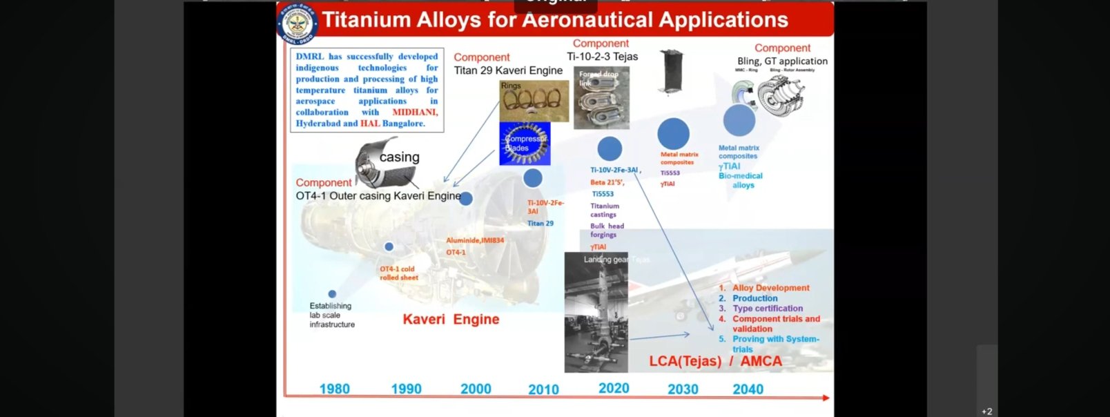
https://x.com/shreedharsingh9/status/18 ... 2097590634
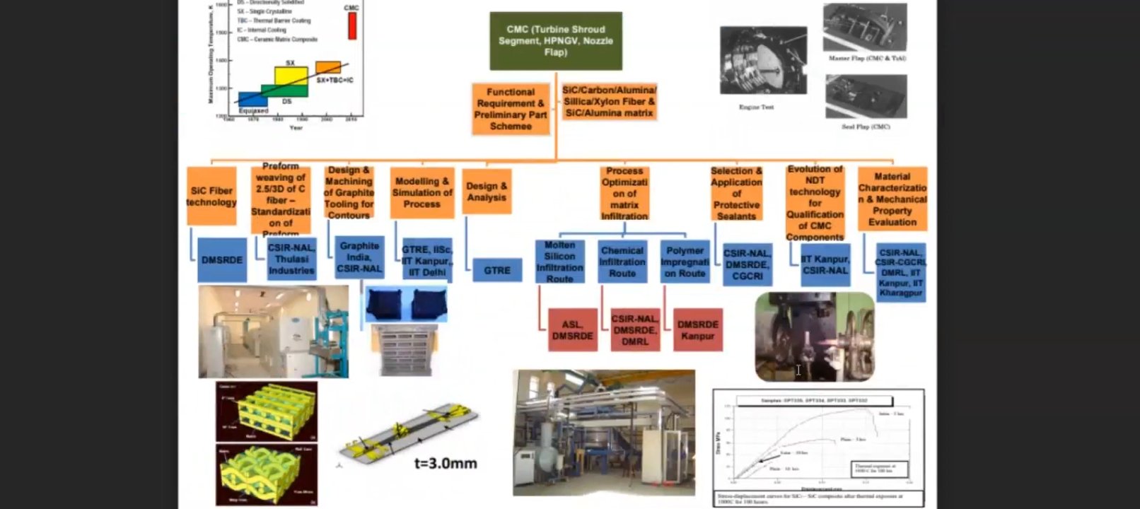
https://x.com/shreedharsingh9/status/18 ... 7679018347
https://x.com/shreedharsingh9/status/18 ... 2714256597
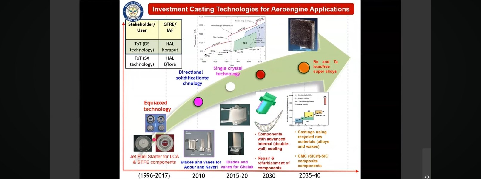
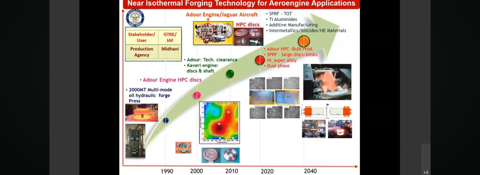
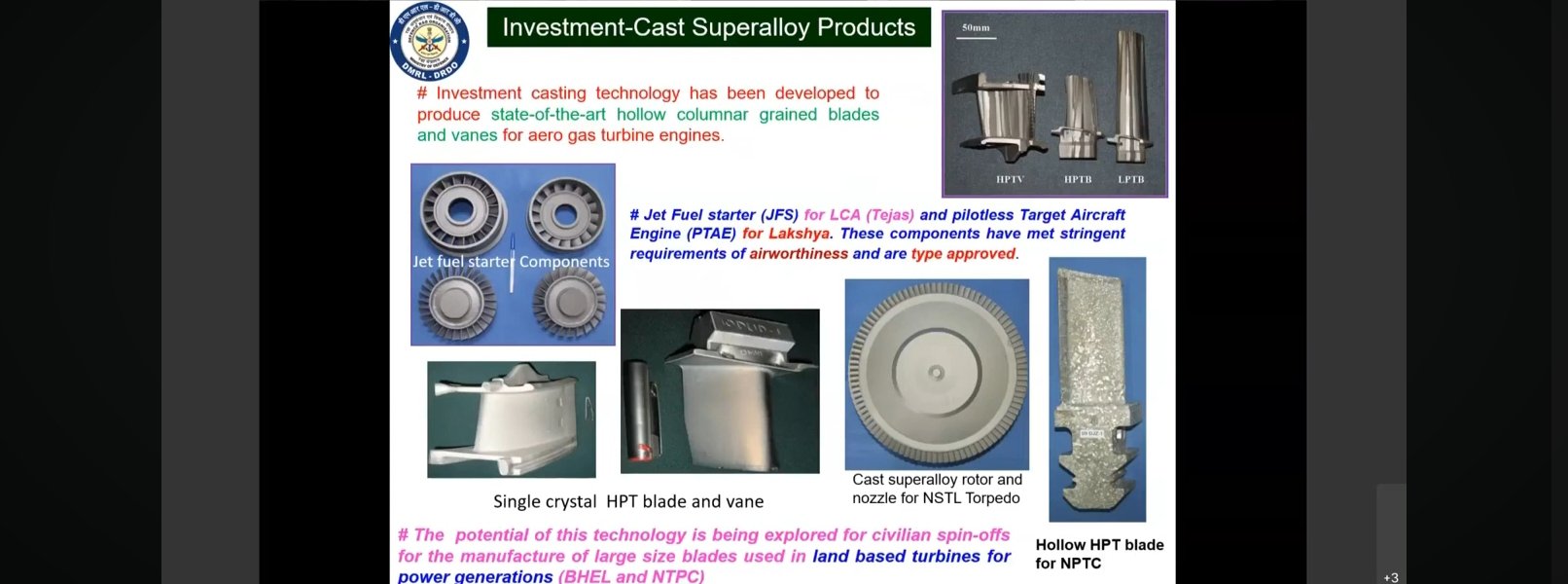
Advance materials developed by Drdo for Jet engine
https://x.com/shreedharsingh9/status/18 ... 2097590634
Road map for development of CMC part for indigenous engine
https://x.com/shreedharsingh9/status/18 ... 7679018347
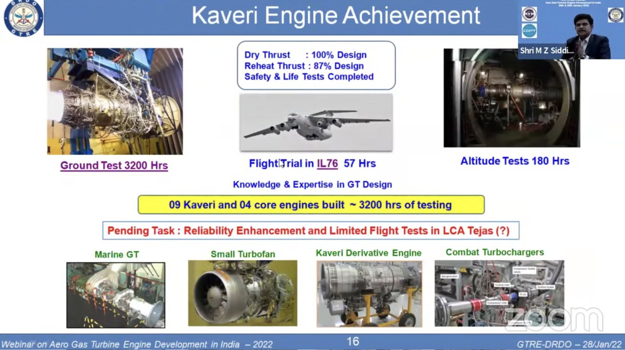
Kaveri Derivative Engine
Re: Kaveri & Aero-Engine: News & Discussion
Nothing new, but a confirmation nevertheless, on the AMCA (Ph 2) engine co-dev partner selection exercise.
Re: Kaveri & Aero-Engine: News & Discussion
https://x.com/rv_srivatsa/status/1890438771482505513 ---> #Storytime! By one GTRE scientist who told me. To do a first stage compressor blade test in their CTR, it takes about 10 mW of power! But you cannot test it randomly at any time of the day because it disrupts the surrounding residential colony power supply load. So they often run tests in the late evening when power consumption is relatively low on the grid and they can consume their required power safely. This is because currently GTRE has been flanked by residential colonies and a tech park, along with HAL engine division as neighbour. Thankfully the new upcoming 120kN Twin Test Cell Facility will be free of these problems, KPTCL (Karnataka Power Transmission Corporation Limited) has provided dedicated power line with required tolerances. Which makes them do carefree throttled tests and not worry about all this. Small things like this , but they matter. Appreciated this chat with him.
Re: Kaveri & Aero-Engine: News & Discussion
https://x.com/reach_defence/status/1890643799946207721 ---> GTRE DRDO 130 kN Twin Test Facility is progressing very well.
- Civic Infrastructure is expected to be ready by August 2025.
- Test Facilities (Rigs , Stand, Cranes, Monitoring Facilities etc) - expected to be ready by another year from completion of civic works.

https://x.com/alpha_defense/status/1890681856636391525 ---> GTRE's new 130KN Twin Test Facility. Full details soon with HATF and FTB.
- Civic Infrastructure is expected to be ready by August 2025.
- Test Facilities (Rigs , Stand, Cranes, Monitoring Facilities etc) - expected to be ready by another year from completion of civic works.
https://x.com/alpha_defense/status/1890681856636391525 ---> GTRE's new 130KN Twin Test Facility. Full details soon with HATF and FTB.
Re: Kaveri & Aero-Engine: News & Discussion
https://x.com/reach_defence/status/1890728306724483080 ---> Progress with imagery of the 130kN - Twin Test Cell by GTRE , as depicted by historic imagery. Work is progressing at breakneck speeds, 3 years for the facility to be up this much is a feat!

Re: Kaveri & Aero-Engine: News & Discussion
Behind a paywall. If anyone has a link to the full article, please post the link.
MIDHANI working on developing advanced materials for hypersonic applications and next-generation jet engines
https://www.thehindu.com/news/national/ ... 198804.ece
09 Feb 2025
Mishra Dhatu Nigam Limited (MIDHANI), the defence metallurgical and engineering public sector unit, is working on the development of advanced materials for hypersonic applications and next-generation jet engines, to revolutionize aerospace performance in the coming years.
Re: Kaveri & Aero-Engine: News & Discussion
Pretty generic article which casually mentions mastering of intermetallic like TiAl for TF applications - and that's about it.Rakesh wrote: ↑17 Feb 2025 22:08 Behind a paywall. If anyone has a link to the full article, please post the link.
MIDHANI working on developing advanced materials for hypersonic applications and next-generation jet engines
https://www.thehindu.com/news/national/ ... 198804.ece
09 Feb 2025
Mishra Dhatu Nigam Limited (MIDHANI), the defence metallurgical and engineering public sector unit, is working on the development of advanced materials for hypersonic applications and next-generation jet engines, to revolutionize aerospace performance in the coming years.
Even wrt TiAl, it doesn't clarify if they are talking about gamma-TiAl or not, explicitly - but I think that's what they are alluding to.
Have written extensively on γ-TiAl usage in a TF - especially wrt the γ-TiAl-with Nb. So no point in belaboring them anymore, one can always read them up, if one is interested in it.
Mastering γ-TiAl for LPT blades (e.g. LP turbine blades of GEAE (CF6 engine), M88-2 etc) preferably via Laser sintering 3D tech (SLM/SLT) is a game changer for any TF dev program - also γ-TiAl is used in the last stages of the HPC.
Let's see ...
Re: Kaveri & Aero-Engine: News & Discussion
India's Quest For Indigenous Aero Engine For LCA Tejas & AMCA Fighter Jets | GTRE Director Explains!
India's premier research laboratory on Aero Engine, the Gas Turbine Research Establishment (GTRE), a DRDO laboratory has been developing an Aero Engine for long. What it takes to develop an aero engine for 4th generation plus and 5th generation plus aircraft? What has happened to India's Kaveri Engine Program? Is India still developing a potent aero engine with a weight to thrust ration that suits user Indian Air Force? What are the hurdles in the development of engines? Does India has Component Testing Facility, Altitude Testing Facility, Flying Test Bed Facility available in India? What is the budget of India's swadeshi Kaveri Aero Engine? What is the actual budget required for developing an aero engine for India's robust Light Combat Aircraft (LCA) Tejas and Advanced Medium Combat Aircraft (AMCA)? Which is the best way to produce indigenous aero engine at a massive scale that can sent shock waves down the enemy spine? Get to Know all about India's quest for indigenous powerful aero engine by Dr. SV Ramana Murty, Director, GTRE, DRDO in this exclusive interview with National Defence founder Editor, Shailesh Kumar.
This YT video is straight from the Director of GTRE, Dr. SV Ramana Murthy chatting with National Defence founder Editor, Shailesh Kumar.
// I am not competent enough to know whether Director has revealed any new gyan on Kaveri engines. One thing he did mention is that the other HAL cruise missile turbo fan engine is successful. He mentioned certain slight under-performance of Kaveri from the stated specs, which can be improved by metallurgy.
// I think we can fly the slight under performance engine in actual flights and once the improvements are made, swap engines out. Tis the cost of R&D and learning curve.
// the common refrain is unavailability of test beds to test things which costs in the $ 5-10 B ( roughly Rs 1 lakh crore) ranges but these are things that India should be willing to shell out since in the scheme of things they are still peanuts compared to buying abroad for everything.
Re: Kaveri & Aero-Engine: News & Discussion
I'd seen that interview, and there's, as usual, no specifics asked or discussed - happens all the time, when the interviewer(s), are of 0-technological-capability. The GTRE dir though, tried his best to bring-in technological aspects a couple of times, but with 0-follow-up tech questions, couldn't do much wrt sustaining the discussion.bala wrote: ↑19 Feb 2025 00:56 This YT video is straight from the Director of GTRE, Dr. SV Ramana Murthy chatting with National Defence founder Editor, Shailesh Kumar.
// I am not competent enough to know whether Director has revealed any new gyan on Kaveri engines. One thing he did mention is that the other HAL cruise missile turbo fan engine is successful. He mentioned certain slight under-performance of Kaveri from the stated specs, which can be improved by metallurgy.
// I think we can fly the slight under performance engine in actual flights and once the improvements are made, swap engines out. Tis the cost of R&D and learning curve.
// the common refrain is unavailability of test beds to test things which costs in the $ 5-10 B ( roughly Rs 1 lakh crore) ranges but these are things that India should be willing to shell out since in the scheme of things they are still peanuts compared to buying abroad for everything.
[rant]After all, to ask anything you need some level of basic understanding atleast, which obviously is missing - typical of the so-called media circus that one witnesses nowadays. It seems, all one needs is a pair of microphones and few cameras, and one can easily parade their ignorance in full public view - but then again, if that's what public in general finds acceptable, then who the hell am I to complain or talk about it. In fact, nowadays, with the TSP threads and pinglish etc drying up, I do watch them for the free entertainment that is readily available. And lately I've noticed, whenever some TV anchor is trying their best to appear serious while discussing about a defence technology or D&D topic, the more hilarious they become (wrt their utter lack of common sense or even basic arithmetic or basic logic etc). Sad part is, wrt some of the eggsperts who adorn these shows, also quite shamelessly try to toe the viewpoint that these so-called anchors are trying to force on everyone, even when they know much better about the real facts etc - maybe, that way, it ensures their continuous tv-show invites, from these media houses.[/rant]
Anyway, coming back to the topic in hand, only following points that I could glean from it - but I'm sure I may have a missed quite a few, as after 5-6mins or so, had completely lost interest in it - had let the video just play along:
1) The approach to engine development has changed nowadays - currently the aim to first develop all the relevant technologies stand-alone first, before embarking on a product dev where these developed/proven technologies are then integrated together.
Earlier products were developed first and technology development happened in parallel - e.g. (from me) is the original LCA program vis-a-vis the current AMCA program.
2) The indigenous TF ecosystem is at a mind-blowing level - simply no comparison of what it was when Kaveri was getting designed/developed in late 90s/early 2000s. So much so that ALL of these TF MSMEs have graduated to be part of tier-1-supply-chain of ALL global OEMs (for their various products both civilian and military) - and today, there's a high chance that if GTRE et all approach them with a request to manufacture (low vol) a part etc, they may decline saying that their installed capacity is already full, delivering to these OEMs.
3) The transition from D&D to mfg phases has been smoothed out by ensuring these MSMEs get involved in the prototype dev of the D&D phases (e.g., again mine, Godrej, PTC et all for the dry Kaveri Program)
4) Wrt SC usage in HPT etc, he did fleetingly mention about using CMSX4* superalloy, but the raw material is being imported (obviously).
Actually he did touch on various stages/phases of a Turbine blade mfg technologies (pls refer to my earlier posts wrt details on each of them), but since there was no follow-up question (the interviewer was quite lost, at mere mention of those terms), the topic stopped then and there.
Ditto wrt TBC and EBPVD tech.
5) He also fleetingly mentioned about PM discs and the new 50K Ton press facility (which is of dual use, applicable both for turbine discs and monolithic bulkhead mfg) being setup at HAL etc.
6) And of course, original Kaveri achieving 95% (he said 5% miss) of the required dry thrust levels - and that there are no High ALt Test facility or FTB etc available in country, and the program bottlenecks that they caused etc etc - nothing that we haven't discussed here, over last couple of decades.
7) He did mention the absence of TF-relevant rare-earth minerals like Y etc (though he mistakenly mentioned Re, Ru etc, as well, which are transition elements), indigenously - and the need to setup "mineral-banks", which all established countries like US, China et all are doing anyway.
etc, etc.
================================================================================================================
* As it is well known here, CMSX4 is a 2nd Gen SC Superalloy - the least the interviewer could have done was query about indigenous DMS4 (4th Gen SC Superalloy), and the plans of using it in our TF programs.
But then again for that, one needs to know about various Gen SCs in the first place.
-
dinesh_kimar
- BRFite
- Posts: 546
- Joined: 11 Aug 2016 06:14
Re: Kaveri & Aero-Engine: News & Discussion
Wow! I saw the above video and he clearly says the Kaveri makes 49 KN dry thrust.
With an afterburner thrust augmentation of 58% , we get 78 KN, I believe.
Our first LCA Tejas flight had GE engines with 77.8 KN.
His bottlenecks seems to be the FTB and Altitude Test Facility, paving the way for Aircraft integration.
With an afterburner thrust augmentation of 58% , we get 78 KN, I believe.
Our first LCA Tejas flight had GE engines with 77.8 KN.
His bottlenecks seems to be the FTB and Altitude Test Facility, paving the way for Aircraft integration.
Re: Kaveri & Aero-Engine: News & Discussion
Someone really proficient should do a proper interview of GTRE/DMRL folks to bring out specific question and answers for the same. Really hoped substantial would come out of AI2025....
Re: Kaveri & Aero-Engine: News & Discussion
First we need to test bed Aircraft, this going to Russia then waiting 6 months before the Russians are willing is stupid.
Re: Kaveri & Aero-Engine: News & Discussion
Maitya ji,
Asking from a noob perspective....
The thrust to weight ratio of the Kaveri was around 6, with the design requirement of 10. For the 6th gen engines that target is around 14.
It wasn't quite apparent how they can get from 6 to 10. The generic answer is 'we need to collaborate with a foreign engine partner'.
To a lay person like me, it seems like a pretty huge miss.
-
Nalla Baalu
- BRFite
- Posts: 159
- Joined: 24 Aug 2006 07:16
- Location: Yerramandi, Dhoolpeta
Re: Kaveri & Aero-Engine: News & Discussion
I recall from the video that the T/W target for Kaveri was 8. It acieved 6.5. He mentioned three pathways to bridge the gap: higher turbine entry temp, blisks and bolt-less turbine stages. Presumably the first to increase thrust and the latter two to reduce weight.
The T/W target for Gen 5 is 10 and Gen 6 is 14.
The T/W target for Gen 5 is 10 and Gen 6 is 14.
Re: Kaveri & Aero-Engine: News & Discussion
If a higher turbine entry temp is desired, does that mean more fuel is burned? Would that require a higher air flow?Nalla Baalu wrote: ↑20 Feb 2025 00:27 I recall from the video that the T/W target for Kaveri was 8. It acieved 6.5. He mentioned three pathways to bridge the gap: higher turbine entry temp, blisks and bolt-less turbine stages. Presumably the first to increase thrust and the latter two to reduce weight.
The T/W target for Gen 5 is 10 and Gen 6 is 14.
Re: Kaveri & Aero-Engine: News & Discussion
First of all, according to me, there's a slightly mess-up in the question itself ... oh betw, there's no miss or anything!!RCase wrote: ↑19 Feb 2025 23:13 Maitya ji,
Asking from a noob perspective....
The thrust to weight ratio of the Kaveri was around 6, with the design requirement of 10. For the 6th gen engines that target is around 14.
It wasn't quite apparent how they can get from 6 to 10. The generic answer is 'we need to collaborate with a foreign engine partner'.
To a lay person like me, it seems like a pretty huge miss.
A 4th Gen military TF will aim for Thrust-to-Weight ratio of 8 (and not 10, that is for 5th Gen TF - for 6th Gen it's 14), whilst Kaveri (K9) achieved around ~6.8.
But all these are the wet T/W ratio figures - and as I've said multiple times now, that it's never a good idea to consider wet T/W ratio, while trying to understand what needs to be done technologically to upthrust a TF etc, except for maybe while discussing with a bunch of clueless media folks.
The reason of course is, that almost entire technological advancements for upthrusting etc is focused on the core (so Kabini of Kaveri), and thus the Dry Thrust values becomes paramount.
However, this also doesn't mean, the A/B is left unattended - it also does require some level of advancements as well, but let's say, relatively it's a way lesser of an issue, compared to changes to the core-TF, that needs to be bought in.
So the right way to put it is, how does Kaveri K9 achieves dry T/W ratio of ~5.5, that is typical of a 4th Gen TF?
And with Kaveri reaching within the 95% of the design dry thrust levels, not much needs to be done actually. Also remember, with the dry-Kaveri achieving TWR of ~5.2, frankly achieving 4th Gen level perf, is more or less already achieved.
At a very high level, what is lacking in K9 vis-a-vis a contemporary 4th Gen TF (like M88-2, EJ-200 etc) are:
1) Weight - it needs to achieve these thrust levels at around 975-990Kg levels - so ~150Kg weight reduction, which is where advanced PMC, MMC, CMC etc based accessories (and shrouds, casings etc) comes into play.
2) The last-mile 5% (or even 7-8%) dry-level upthrusting - this can be achieved in a relatively low-risk approach of getting a lighter LPT (e.g. usage of intermetallic gamma-TiAl for the LPT blades a la M88-2) and a better designed Fan.
As you may have noticed that such a tinkering leaves alone the hot-core section, which is infinitely riskier to touch/tinker upon.
Anyway Kaveri's Fan rpm is quite underwhelming (for example comparing with the rpm of F404 fan), and there's a lot of scope of improving it.
Having said that, for a low-BPR design, LP complex (LPT-Fan) improvements, wouldn't translate to the overall thrust-improvements, as much as it would done for a relatively higher-BPR design like a F404 or M88-2 or EJ-200 etc.
Also needs to be considered here is, just how much of dry T/W will these non-flat-rated 4th Gen TFs actually achieve in vast swaths of our sub-continental operating conditions, their technicolor brochures be damned.
For achieving the wet TWR level of 8 (from current ~6.8 ), any further improvements in the dry thrust ratings, as discussed above, will anyway boost the overall TWR anyway - but yes, some work is also required on the A/B section, to ensure 60% boost above the dry-thrust levels (while keeping mass-fraction to <1.1).
Wrt Kaveri program in particular, there's actually a roadmap of upthrusting it further, you may want to refer to this old post (report from Alpha Defense).
Now things become interesting, if one is asking to graduate the current 4th Gen Kaveri (say K9/K10) achieve 68KN (dry)/110KN (wet) thrust levels - which essentially means 33% increment in thrust levels.
At the outset, do note that such a quantum-jump is not possible without essentially redesigning a brand-new TF with a bigger dimensional footprint.
However one point gets constantly missed here (and not only by the clueless media), is that such a graduation is possible, without getting into 5th Gen TF technologies.
Aka you can still try to achieve this via the current 4th Gen technologies available, but you'll need to go for bigger dimensions and also sacrifice a lot on the efficiency and other perf parameters (e.g. SFC etc).
Multiple examples galore, one would be the AL-31FP itself.
And let me quote myself from one of my older posts (in this very thread):
Let me say again - enough TF technological (both metallurgical and manufacturing) base exists in the country today to D&D (and Manufacture) a 120KN (or even 130KN) class TF - thanks to Kaveri and HTFE programs.
Yes that may not match up to the 5th Gen F119/F135 or Izdeliya-30 class, but a 4th Gen (or a 4+ Gen) class TF, is very well within our current capabilities.
Anyway, wrt such an upthrusting, well, I've written extensively on this very topic, you may want to go thru them once:
1. [Part-1: Introduction]
2. [Part-2: HPC PR Improvement]
3. [Part-3: HPC PR Improvement via Aerodynamic route]
4. [Part-4: The LPT/FAN route]
5. [Part-5: Epilogue]
But I think your question is more nuanced:
What you are essentially asking is to see if the current 4th Gen Kaveri (say K9/K10) can be graduated to a 5th Gen avatar - which essentially means, asking that within the same form factor, achieve 68KN (dry)/110KN (wet) thrust levels, via an improved TWR of ~10.
Now such an endeavor will involve graduating to whole-new technological gen capability - some of which I'd enumerated in one of my older posts.
And something like that sort has been already tried by GE successfully in their F404 -> F414-GE-400 -> F414-EPE evolution - and a rough-guess of the technologies involved can be understood from this image that Chetakji had posted a few pages back.
Incidentally, in the recent interview during AI25, the GTRE Dir did allude to some of these technologies, being currently under indigenous development.
I'm not getting into 6th Gen etc, as without mastering 5th Gen technologies first, such talks are nothing more than khyali pulao grade - exclusive domain of the assorted media eggsperts who never tire of lecturing about such topics (and in turn, hilariously parade their ignorance in full public view).
=====================================================================================================================================
PS: If you are interested in understand how such evolutions can be modeled (parametrically) you can refer to the following series of my old-posts:
1. Hypothetical Kaveri Mk2 - Modelling Analysis
2. Part-1
3. Part-2
4. Part-3
5. Part-4
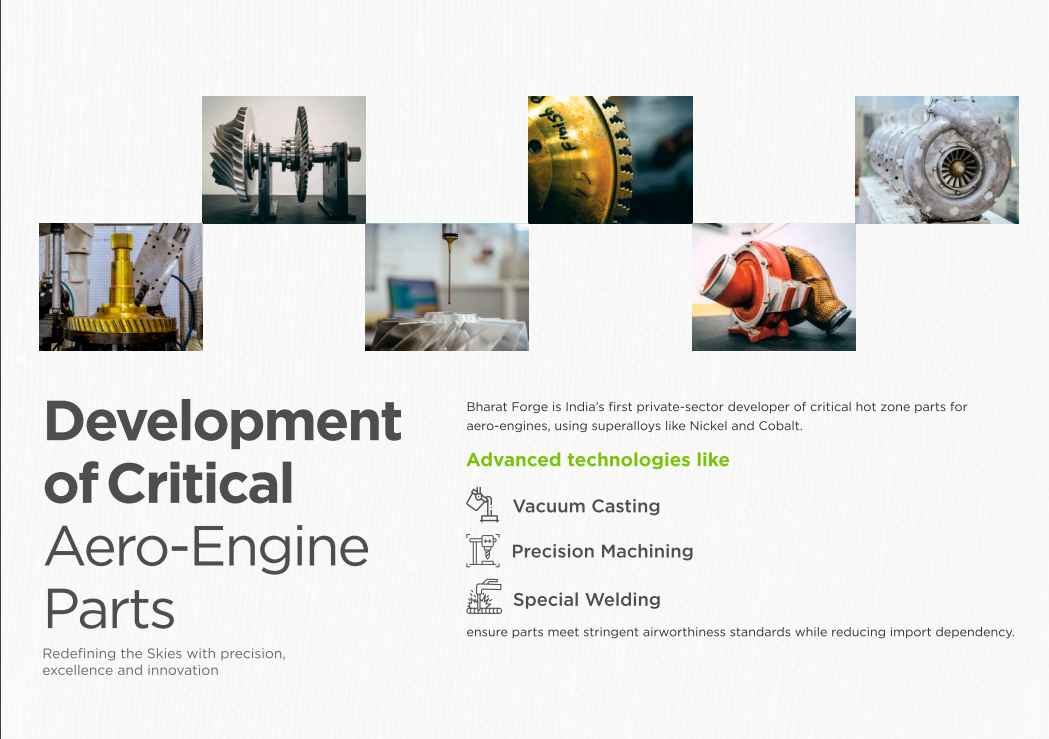
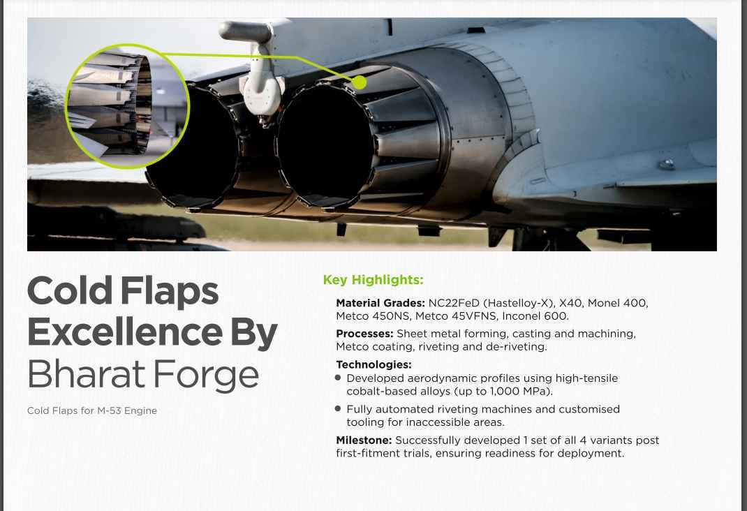
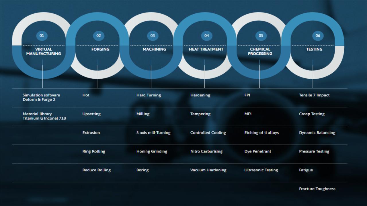

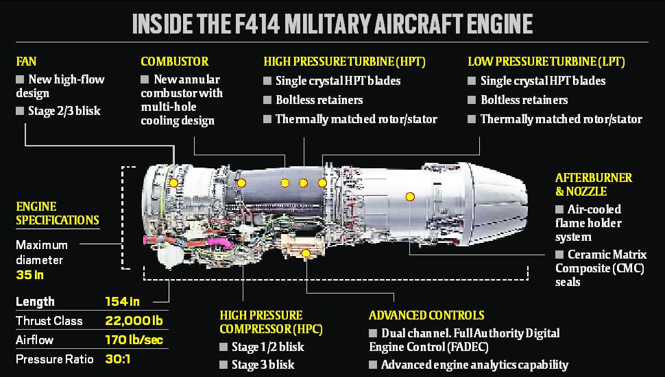
Re: Kaveri & Aero-Engine: News & Discussion
Maitya ji - Thank you for the patient and detailed response. Appreciated the references to the previous posts and your efforts in collating information for easy understanding.
Re: Kaveri & Aero-Engine: News & Discussion
https://x.com/PattyInnovate/status/1892954385707094067 ---> Excited to announce that DG Propulsion has signed a Strategic Agreement with Bharat Dynamics Limited (BDL) to collaborate on jet turbine engines for loitering munitions, high-speed UAVs, and advanced propulsion systems. A big step toward strengthening India's defense capabilities with indigenous technology! PS - If you've got a UAV, we've got the engine @ DG Propulsion to make it fly—faster, higher, and stronger!
https://x.com/PattyInnovate/status/1892969165381599432 ---> Building jet engines is one thing—navigating the system is just flying through mud.
https://x.com/PattyInnovate/status/1892969165381599432 ---> Building jet engines is one thing—navigating the system is just flying through mud.
Re: Kaveri & Aero-Engine: News & Discussion
X-Post from the US military, technology, arms, tactics thread...
https://x.com/RedMeowrine/status/1894094706226991321 ---> My hot take for tonight is that we should disarm most of the Indian military. There's no reason for them to carry guns; maybe an exception can be made for some paramilitary units on the Pakistan border. But otherwise, Gandhi was right.
https://x.com/resistanceenjoy/status/18 ... 9177329870 ---> This is the actual reality. Indian armed forces is a namesake organisation which Nehru and Gandhi did not even want in the first place. The purpose of the Indian state is to suppress the military and ensure it’s in firm civilian control. Rashtriya Rifles, Assam Rifles and RA&W basically manage everything relating to security on their own.
Next time when we wonder why we don't properly fund our own engine program, read below. This has been the attitude of many of our decision makers since 1947.Rakesh wrote: ↑25 Feb 2025 21:33 Air Force triples funding for prototype sixth-gen fighter engine
https://www.defensenews.com/air/2025/01 ... er-engine/
28 Jan 2025
https://x.com/RedMeowrine/status/1894094706226991321 ---> My hot take for tonight is that we should disarm most of the Indian military. There's no reason for them to carry guns; maybe an exception can be made for some paramilitary units on the Pakistan border. But otherwise, Gandhi was right.
https://x.com/resistanceenjoy/status/18 ... 9177329870 ---> This is the actual reality. Indian armed forces is a namesake organisation which Nehru and Gandhi did not even want in the first place. The purpose of the Indian state is to suppress the military and ensure it’s in firm civilian control. Rashtriya Rifles, Assam Rifles and RA&W basically manage everything relating to security on their own.
Re: Kaveri & Aero-Engine: News & Discussion
https://x.com/shiv_cybersurg/status/1893156492662223205 ---> After many years I found out what had been ailing our dear Kaveri engine. They never revealed the issue, but then again I don't blame them because snakes in engine industries abroad would raise prices of just the stuff we were failing in. A talk by a GTRE director and Aero India revealed the truth. What the Kaveri was suffering from was "Fan flutter" in the front section that was leading to the "excessive noise" that was rumored to have been there. But worse than noise was that this could cause:-
1. Catastrophic engine failure
2. Inability to throttle up and down freely as required for a fighter engine
https://x.com/shiv_cybersurg/status/1893156499272466497 ---> The front - low pressure compressor - section of the new Kaveri Derivative engine (circled in yellow) in the image has been completely redesigned and there is no more flutter and free throttling up and down has been demonstrated. That front section was the root of the problem in the original Kaveri. Hopefully this new Kaveri derivative engine will actually be flown. Atmanirbharta demands it. And hopefully they will eventually add and afterburner and use a twin engine solution for an Indian aircraft.
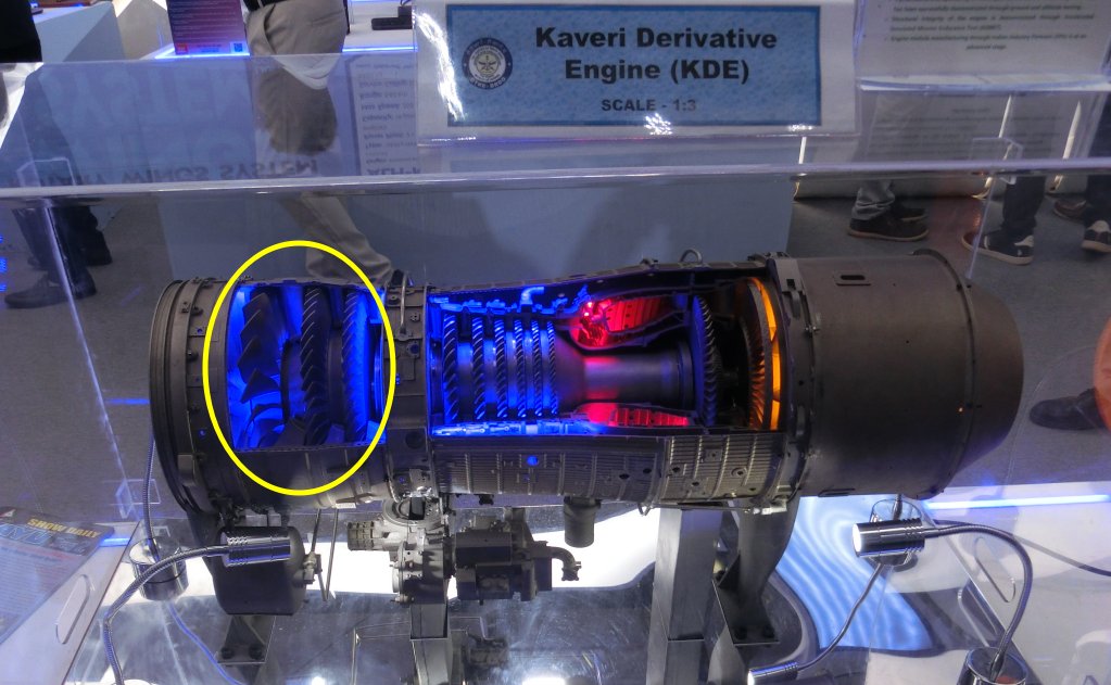